Table 1.d – Rockwell Automation LPM20 Liquid-Cooled AC Drive with High Performance Drive Control User Manual
Page 30
1-18
Installation/Wiring
Installing a Required External/Separate Input Disconnect
An input disconnect must be installed in the line before the drive input
terminals in accordance with local, national, and international codes (e.g.,
NEC/CEC). The disconnect should be sized according to the in-rush current
as well as any additional loads the disconnect might supply. The trip rating
for the inrush current (10-12 times full load current) should be coordinated
with that of the input isolation transformer, if used. Refer to
Transformers and Reactors (Not Recommended) on page 1-17
additional information.
Installing Power Wiring from the Input Filter Section to the Power
Module
Use the following steps to connect AC input power to the drive:
1. Connect the three-phase AC input power leads (three-wire 380-480
VAC) to the appropriate terminals.
2. Tighten the AC input power terminals to the proper torque as shown in
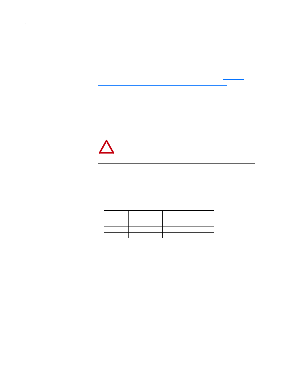
Table 1.D Terminal Tightening Torques
!
ATTENTION: Do not route signal and control wiring with
power wiring in the same conduit. This can cause interference
with drive operation. Failure to observe this precaution could
result in damage to, or destruction of, the equipment.
Terminals
Hardware Type
Maximum Tightening Torque
(+10%)
L1 to L6
M10, CI. 9.8
43 N-m (31 lb.-ft.)
U, V, W
M10, CI. 9.8
43 N-m (31 lb.-ft.)
GND, PE
M8, CI. 9.8
22 N-m (16 lb.-ft.)