Net a status indicator, Module diagnostic items in single drive mode – Rockwell Automation 22-COMM-D DeviceNet Adapter User Manual
Page 98
8-4
Troubleshooting
The following diagnostic items can be accessed using DriveExplorer
(version 3.01 or higher).
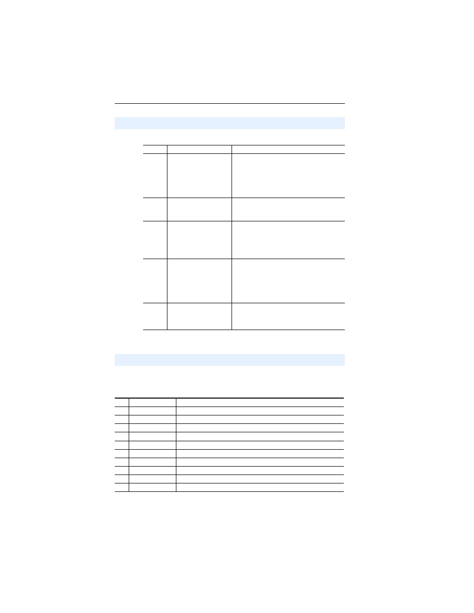
Net A Status Indicator
Status
Cause
Corrective Actions
Off
The adapter and/or
network is not powered or
adapter is not connected
properly to the network.
• Securely connect the adapter to the drive
using the Internal Interface cable and to the
network using a DeviceNet cable.
• Correctly connect the DeviceNet cable to the
DeviceNet plug.
• Apply power to the drive and network.
Flashing
Red
A DeviceNet I/O
connection has timed out.
• Place the scanner in RUN mode, or apply
power to the peer device that will send I/O.
• Check the amount of traffic on the network.
Solid
Red
Failed duplicate node
detection test or bus off
condition exists.
• Configure the adapter to use a unique node
address on the DeviceNet network.
• Configure the adapter to use the correct
network data rate.
• Ensure network has correct media installed.
Flashing
Green
The adapter is properly
connected but is not
communicating with any
devices on the network.
• Place the controller in RUN mode, or apply
power to the peer device that will send I/O.
• Program a controller or peer device to
recognize and transmit I/O to the adapter.
• Configure the adapter for the program in the
controller or the I/O from the peer device.
Solid
Green
The adapter is properly
connected and
communicating on the
network.
No action required.
Module Diagnostic Items in Single Drive Mode
No.
Name
Description
1
Field Flash Cnt
The number of flash updates made to the adapter after shipping.
2
Adapter Events
The number of events in the event queue.
3
Reference
Reference being transmitted to the host by this peripheral.
4
Logic Cmd
Command being transmitted to the host by this peripheral.
5
Logic Sts
Status being received from the host by this peripheral.
6
Feedback
Feedback being received from the host by this peripheral.
7
DN Rx Errors
Current value of the DeviceNet CAN Receive Error Counter register.
8
DN Tx Errors
Current value of the DeviceNet CAN Transmit Error Counter register.
9
Data Rate SW
Current setting of the adapter 2-bit data rate switch.
10
Node Address SW Current setting of the adapter 6-bit Node address switch.