Rockwell Automation 22-COMM-D DeviceNet Adapter User Manual
Page 82
7-10
Using Multi-Drive Mode
Drive 0 - Drive 4 Control Routines
The Drive Control routines provide status information (Logic Status and
Feedback), control (Logic Command and Reference), and parameter
read/write for each of the respective drives. See
for Drive 0,
for Drive 1,
for Drive 3,
and for Drive 4.
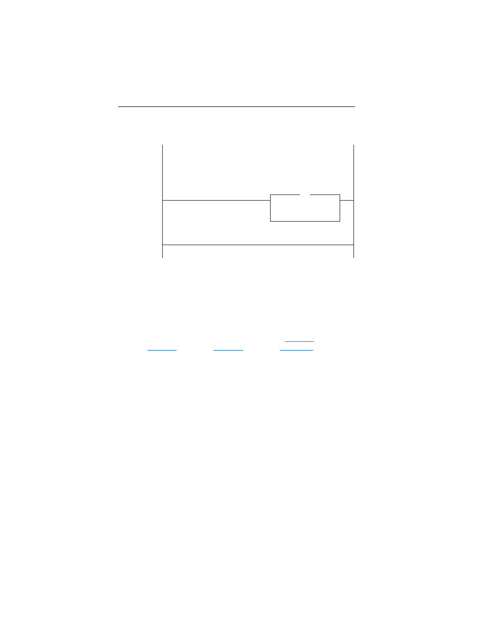
Figure 7.6 Main Routine (Continued)
This section writes the output image to the scanner. The output image is as follows:
DriveOutputImage[0] and DriveOutputImage[1] = Drive 0 Logic Command and Reference
DriveOutputImage[2] and DriveOutputImage[3] = Drive 1 Logic Command and Reference
DriveOutputImage[4] and DriveOutputImage[5] = Drive 2 Logic Command and Reference
DriveOutputImage[6] and DriveOutputImage[7] = Drive 3 Logic Command and Reference
DriveOutputImage[8] and DriveOutputImage[9] = Drive 4 Logic Command and Reference
(Note the length of the COP instruction is "5" because the Destination address is a DINT)
7
Copy File
Source DriveOutputImage[0]
Dest
Local:3:O.Data[0]
Length
5
COP
This section writes the output image to the scanner. The output image is as follows:
DriveOutputImage[0] and DriveOutputImage[1] = Drive 0 Logic Command and Reference
DriveOutputImage[2] and DriveOutputImage[3] = Drive 1 Logic Command and Reference
DriveOutputImage[4] and DriveOutputImage[5] = Drive 2 Logic Command and Reference
DriveOutputImage[6] and DriveOutputImage[7] = Dr e 3 Logic Command and Reference
DriveOutputImage[8] and DriveOutputImage[9] = Drive 4 Logic Command and Reference
(Note the length of the COP instruction is "5" because the Destination address is a DINT)
(End)