Understanding the i/o image, Using logic command/status – Rockwell Automation 22-COMM-D DeviceNet Adapter User Manual
Page 46
5-2
Using I/O Messaging
The DeviceNet specification requires that the terms input and output be
defined from the scanner’s point of view. Therefore, Output I/O is data
that is output from the scanner and consumed by the DeviceNet adapter.
Input I/O is status data that is produced by the adapter and consumed as
input by the scanner. The I/O image table will vary based on the:
• Configuration of the Mode Jumper (J2) on the adapter and
Parameter 15 - [DSI I/O Cfg]. The image table always uses
consecutive words starting at word 0.
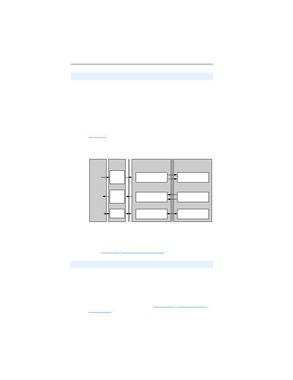
illustrates an example of a Single drive I/O image (16-bit words).
Figure 5.1 Single Drive Example of I/O Image
Single drive mode is the typical configuration, where one node consists
of a PowerFlex 40 drive with a 22-COMM-D adapter.
For Multi-Drive mode, where one node can consist of up to 5 drives,
refer to
When enabled, the Logic Command/Status word is always word 0 in the
I/O image. The Logic Command is a 16-bit word of control produced by
the scanner and consumed by the adapter. The Logic Status is a 16-bit
word of status produced by the adapter and consumed by the scanner.
This manual contains the bit definitions for compatible products
available at the time of publication in
. For other products, refer to their documentation.
Understanding the I/O Image
Controller
Scanner
Adapter
PowerFlex 40 Drive
DeviceNet
DSI
Output
Image
(Write)
Input
Image
(Read)
Message
Handler
Message
Buffer
0 Logic Status
1 Feedback
Logic Status
Feedback
Word and I/O
Message
Handler
0 Logic Command
1 Reference
Logic Command
Reference
Using Logic Command/Status