Rockwell Automation 22-COMM-E EtherNet/IP Adapter User Manual
Page 42
4-6
Configuring the Scanner or Bridge
words and Logic Status/Feedback uses 2 words. The additional 2
words for the inputs are for ENBT overhead.
Table 4.A Input/Output Size Configurations
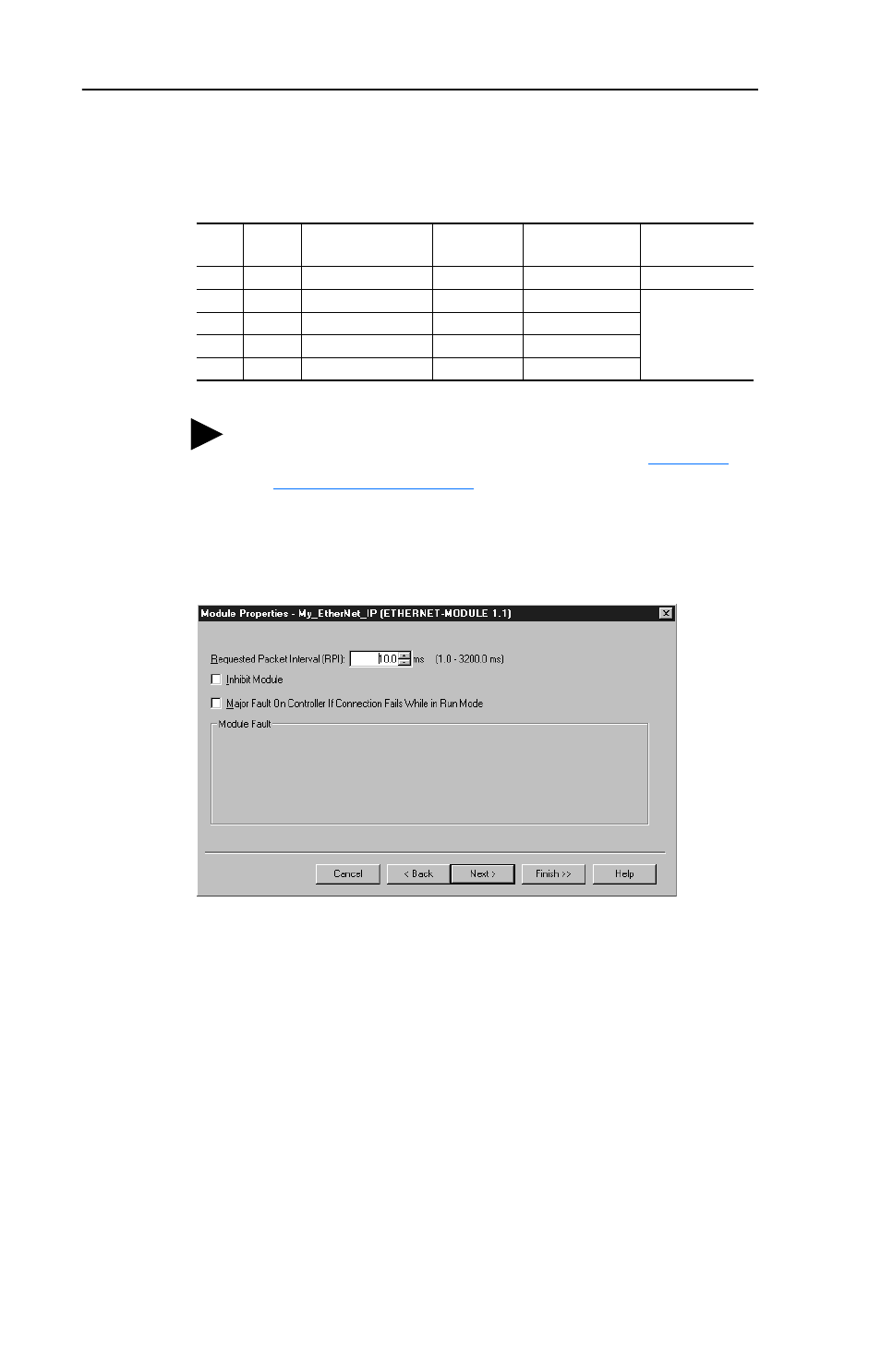
5. Click Next > to display the next page.
Figure 4.9 Module Properties Dialog Box - Page 2
6. In the Requested Packet Interval (RPI) box, set the value to 5.0
milliseconds or greater. This value determines the maximum interval
that a controller should use to move data to or from the adapter. To
conserve bandwidth, use higher values for communicating with low
priority devices.
7. Click Finish>>. The new node (“PF40_Demo” in this example) now
appears under the scanner or bridge (“1756-ENBT” in this example)
in the I/O Configuration folder. If you double-click the Data Types
folder and then double-click on the Module-Defined folder, you will
see that module-defined data types and tags have been automatically
created. After you save and download the configuration, these tags
allow you to access the Input and Output data of the adapter via the
controller’s ladder logic.
Input
Size
Output
Size
Logic Command/
Status
Reference/
Feedback
Parameter 22 -
[DSI I/O Cfg]
Parameter 1 -
[Mode]
4
2
✔
✔
Drive 0
Single
6
4
✔
✔
Drives 0-1
Multi-Drive
8
6
✔
✔
Drives 0-2
10
8
✔
✔
Drives 0-3
12
10
✔
✔
Drives 0-4
TIP: For instructions on configuring the I/O for the
adapter (Parameter 22 - [DSI I/O Cfg]), see
Chapter 3
,
Configuring the Adapter
.