Rockwell Automation 22-COMM-E EtherNet/IP Adapter User Manual
Page 41
Configuring the Scanner or Bridge
4-5
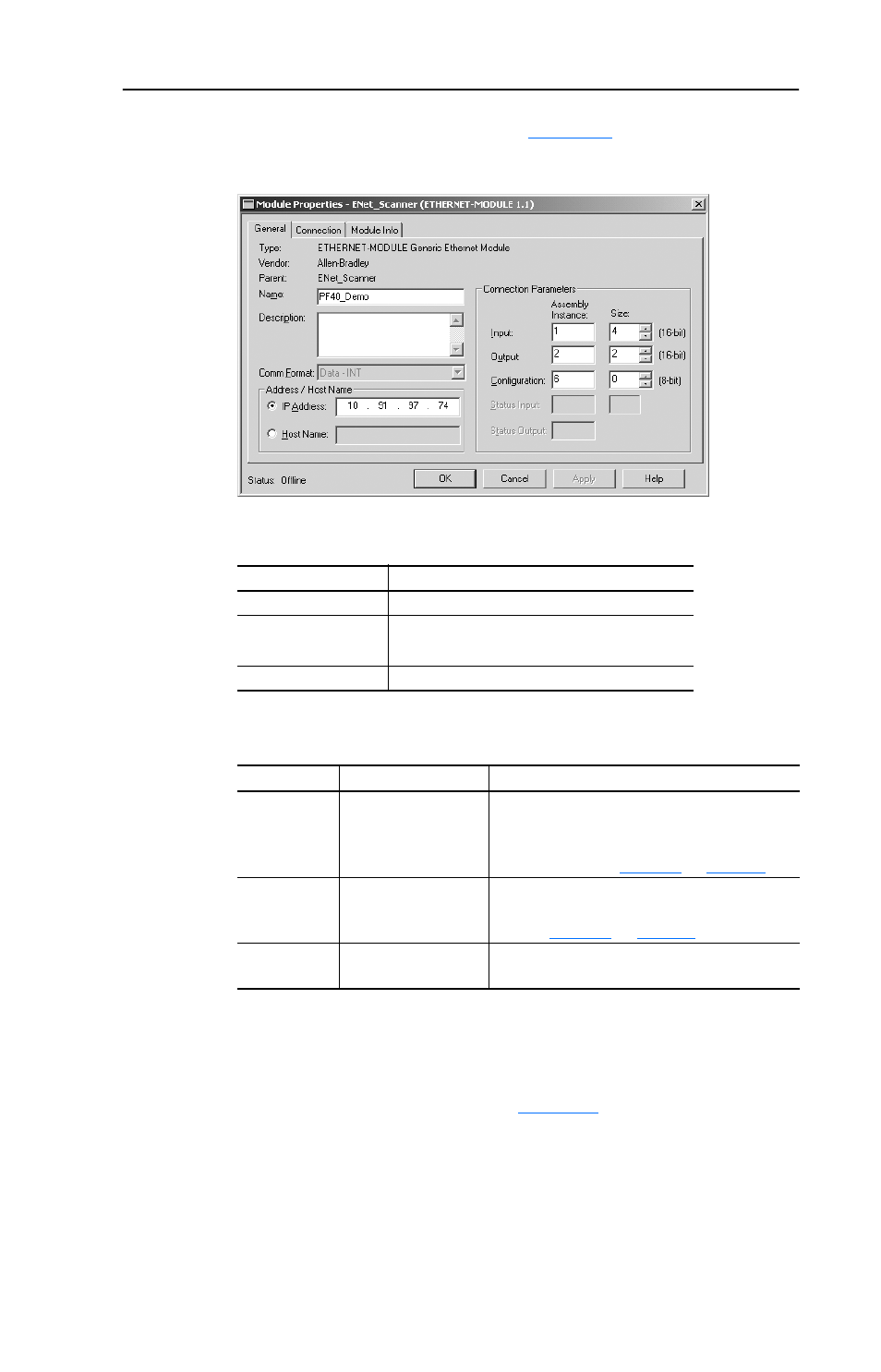
The Module Properties dialog box (
Figure 4.8
) appears.
Figure 4.8 Module Properties Dialog Box - Page 1
3. Edit the following information about the adapter:
4. Under Connection Parameters, edit the following:
Type the number of bytes that are required for your I/O in the Input
Size and Output Size boxes. The size will depend on the I/O that you
enabled in the adapter. This information can be found in Parameter
22 - [DSI I/O Cfg] in the adapter.
Table 4.A
shows common
configuration Input/Output sizes.
In our example, we typed 4 in the Input Size and Output Size boxes
because the Operating Mode Switch on the adapter is set to “Single”
(default) and Parameter 22 - [DSI I/O Cfg] is set to “Drive 0” (only
one drive being connected). Logic Command/Reference uses 2
Box
Type
Name
A name to identify the adapter and drive.
Comm. Format
Data - INT.
This setting formats the data in 16-bit words.
IP Address
The IP address of the adapter.
Box
Assembly Instance Size
Input
1 (This value is
required.)
The value will vary based on your application
(setting of Parameter 22 - [DSI I/O Cfg]). It
will contain 2 additional words for ENBT
overhead. Refer to
Table 4.A
on
page 4-6
.
Output
2 (This value is
required.)
The value will vary based on your application
(setting of Parameter 22 - [DSI I/O Cfg]).
Refer to
Table 4.A
on
page 4-6
.
Configuration 6 (This value is
required.)
0 (This value is required.)