Ladder logic program, Figure 5.4 – Rockwell Automation 20-COMM-R Remote I/O Adapter User Manual
Page 68
5-10
Using Block Transfer Messaging
20-COMM-R Remote I/O Adapter User Manual
Publication 20COMM-UM004D-EN-P
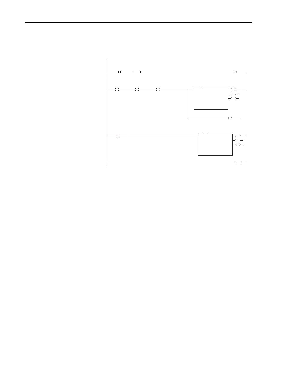
Ladder Logic Program
Figure 5.4 PLC-5 Example Ladder Logic for Block Transfer Messaging
The word length used in the BTW and BTR must be equal to 20, 30, or 60.
It must also be greater than or equal to the byte length used in Word 0 of the
message, converted to words (1 word = 2 bytes).
The user initiates a messaging transaction by setting the User Execute Message Input bit true. This causes one messaging BTW to be sent to the 20-COMM-R.
0000
N7:2
0
User
EXECUTE MESSAGE
Input
ONS
B3:0
1
L
B3:0
0
Execute Message
This rung causes one messaging BTW to execute when the 20-COMM-R is ready to receive a Messaging BTW and the user has requested the BTW.
0001
B3:0
0
Execute Message
I:010
11
Messaging BT
BTW AVAILABLE
Status
I:010
12
Messaging BT
BTR AVAILABLE
Status
EN
DN
ER
BTW
Block Transfer Write
Module Type Generic Block Transfer
Rack
001
Group
0
Module
0
Control Block
BT9:2
Data File
N12:0
Length
20
Continuous
No
BTW
U
B3:0
0
Execute Message
This rung will wait until a BTR is available from the 20-COMM-R module and then execute a BTR.
0002
I:010
12
Messaging BT
BTR AVAILABLE
Status
EN
DN
ER
BTR
Block Transfer Read
Module Type Generic Block Transfer
Rack
001
Group
0
Module
0
Control Block
BT9:3
Data File
N13:0
Length
20
Continuous
No
BTR
0003
END