Setting the configuration dip switches – Rockwell Automation 20-COMM-R Remote I/O Adapter User Manual
Page 19
Installing the Adapter
2-3
20-COMM-R Remote I/O Adapter User Manual
Publication 20COMM-UM004D-EN-P
The Rack Address Rotary Switch settings can be verified (as a decimal
value) by viewing Diagnostic Device Item number 29 (
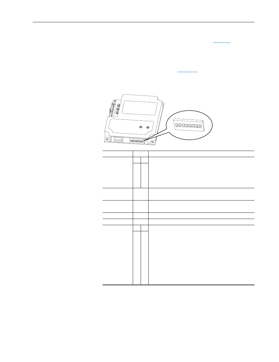
Setting the Configuration DIP Switches
Set the Configuration DIP Switches (
) to match your application
specifics for the controller and network.
Figure 2.2 Setting the Configuration DIP Switches
The Configuration DIP Switches SW7 and SW8 settings can be verified by
viewing Parameter 24 - [Switches] with any of the following drive
configuration tools:
• PowerFlex HIM
• Connected Components Workbench software, version 1.02 or later
• Drive Explorer software, version 2.01 or later
• DriveExecutive software, version 3.01 or later
Switches
Setting Description
SW1 and SW2
1
2 SW1 and SW2 are used together to set the starting module group:
0
0 Group 0 (Default)
1
0 Group 2
0
1 Group 4
1
1 Group 6 – Only used if SW4 is set to “0” (1/4 rack).
SW3
0
Not the last RIO rack (Default)
1
Last RIO group within the rack
SW4
0
1/4 rack (Default)
1
1/2 rack
SW5
0
Not Used
SW6
0
Not Used
SW7 and SW8
7
8 SW7 and SW8 are used together to set the Remote I/O baud rate:
0
0 57.6 kbps (Default)
1
0 115.2 kbps
0
1 230.4 kbps
1
1 Disables all hardware switches. Instead, the adapter uses the values
of the following parameters:
• Parameter 3 - [RIO Addr Cfg] for the rack address
• Parameter 5 - [RIO Rate Cfg] for the baud rate
• Parameter 25 - [Start RIO Group] for the starting module group
• Parameter 26 - [Last RIO Rack] for the last physical rack
• Parameter 27 - [Rack Size] for the rack size
ON
1 2 3 4 5 6 7 8
On = 1
Off = 0