Applying power, Start-up status indications, Applying power -8 – Rockwell Automation 20-COMM-R Remote I/O Adapter User Manual
Page 24
2-8
Installing the Adapter
20-COMM-R Remote I/O Adapter User Manual
Publication 20COMM-UM004D-EN-P
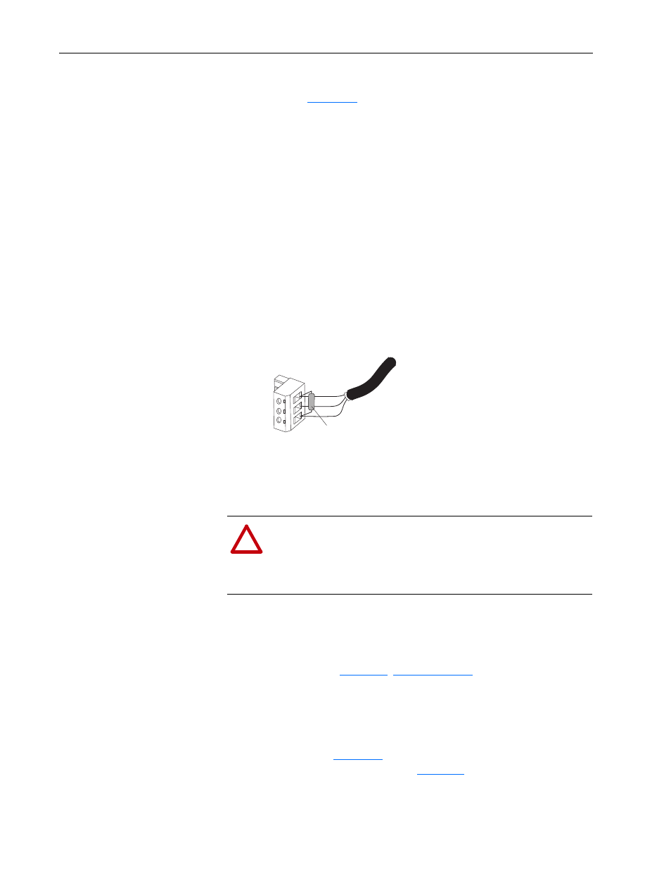
6. If the adapter is at the end of the Remote I/O link, connect a termination
resistor (see
The resistor should have a value of 82 or 150 ohms (82 ohms is
preferred).
Important: If the Remote I/O network is operating at 230.4 Kbps, an
82 ohm termination resistor must be used.
Important: If any of the following products, which cannot operate at
230.4 Kbps, are on the Remote I/O network, a 150 ohm
termination resistor must be used.
Figure 2.7 Connecting a Termination Resistor (if required)
7. Connect the Remote I/O cable plug to the adapter’s mating connector.
Applying Power
Install the drive cover or close the drive door, and apply power to the drive.
The adapter receives its power from the connected drive. When you apply
power to the adapter for the first time, its topmost ‘PORT’ status indicator
should be steady green or flashing green after an initialization. If it is red,
there is a problem. See
Start-Up Status Indications
Status indicators for the drive and communication adapter can be viewed on
the front of the drive (
Figure 2.8
) after power has been applied. Possible
start-up status indications are shown in
Table 2.A
.
• 1771-SN scanner
• 6008-SQH1 scanner
• 1772-SD scanner
• 6008-SQH scanner
• 1772-SD2 scanner
• 1771-AS adapter
• 1772-SR scanner
• 1772-ASB (Ser. A) adapter
• 1775-S4A scanner
• 1771-DCM adapter
• 1775-S4B scanner
• 1771-AF device
Clear
Termination Resistor
(82 Ohms or 150 Ohms)
Shield
Blue
!
ATTENTION: Risk of equipment damage, injury, or death
exists. Unpredictable operation may occur if you fail to verify
that parameter settings are compatible with your application.
Verify that settings are compatible with your application before
applying power to the drive.