Slc 500 controller examples, Slc 500 controller example -17 – Rockwell Automation 20-COMM-R Remote I/O Adapter User Manual
Page 53
Using Discrete and Block Transfer I/O
4-17
20-COMM-R Remote I/O Adapter User Manual
Publication 20COMM-UM004D-EN-P
SLC 500 Controller
Examples
Examples in this section are provided for SLC 500 Series C controllers with
firmware revision 3.xx and higher, and for SLC 500 controllers all versions.
Series C Controller with Firmware Revision 3.xx and Higher
In a series C, firmware revision 3.xx and higher SLC processor, Block
Transfer Read (BTR) and Block Transfer Write (BTW) instructions can be
used. When the length of the Block Transfer is 18 words or less, the
20-COMM-R adapter knows the Block Transfer is for I/O and not for an
explicit message Block Transfer (Chapter 5). Block Transfer setup is the
same for a 1/4 rack or 1/2 rack configuration. This example is for Rack 1,
Group 4 (the upper half rack).
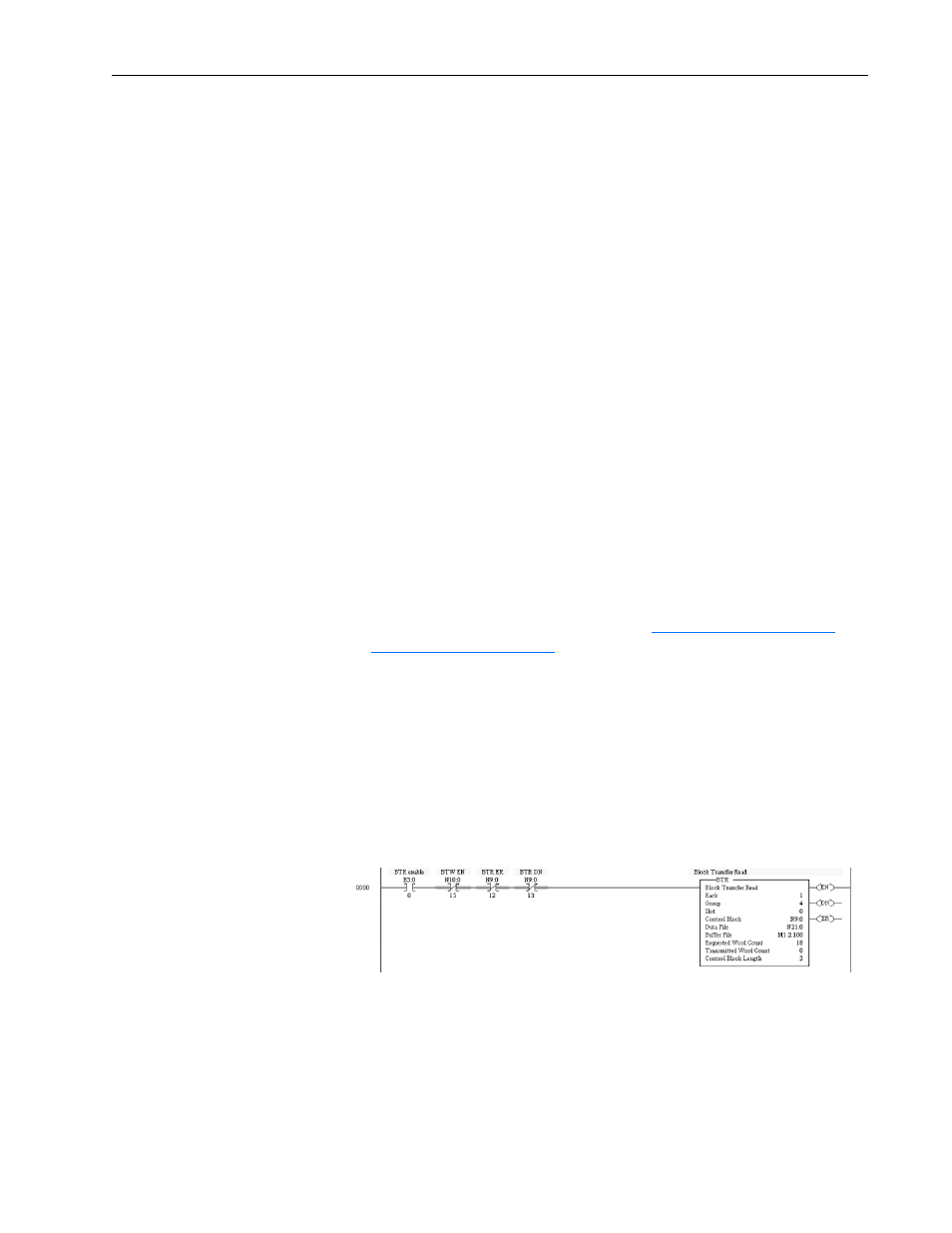
Block Transfer Read Example
The following data is used for this example.
• Rack 1
• Group 4 (upper half rack)
• Slot 0 (always 0)
• Control Block N9:0 (user defined)
• Data File N21:0 (user defined)
• Buffer File M1:x.100 (Block Transfer Reads always start with M1,
where x is the slot in which the 1747-SN scanner card is in. In this
example, the 1747-SN card is in slot 2.)
• Requested Word Count is 18 or less (see
or
)
• Transmitter Word Count (always 0)
• Control Block Length (always 3)
Important: Each Block Transfer needs to be offset by 100 (M1:x.100) and
the default is 3300 words, so you can perform up to 33 Block
Transfers. See the advanced configuration for your 1747-SN
scanner card under channel configuration.
Figure 4.11 SLC 500 Series C, FRN 3.xx and Higher, Example Ladder Logic for
Block Transfer Read