Heatsink fan, Remove components, Install components – Rockwell Automation 20B PowerFlex 700 Drives - Frame 10 Components Replacement User Manual
Page 64: Remove components install components
64
Rockwell Automation Publication 20B-IN026B-EN-P - July 2013
Chapter 3
Inverter Assembly Component Replacement Procedures
Heatsink Fan
See
Chapter 1 - Component Diagrams and Torque Specifications
to locate
components in these instructions.
Remove Components
1. Read and follow the
and
2. Remove safety shields and enclosure covers as needed.
3. Disconnect the green/yellow wire from TB10 to the chassis ground.
4. Carefully cut the plastic wire ties (do not cut the wires), label each wire
from the heatsink fan, and remove the wires from TB10.
5. Remove the mounting bolts (16) for the heatsink fan mounting plate.
6. Carefully remove the mounting plate and fan. You may need to pry the
mounting plate away from the gasket. Remove the gasket if damaged.
7. Remove the four heatsink fan mounting bolts and remove the heatsink fan
from the mounting plate.
Install Components
1. Install the new heatsink fan to the mounting plate. Torque the mounting
screws to 2.9 N•m (26 lb•in).
2. Install the new gasket (if needed) and mounting plate to the chassis.
Torque the mounting screws to 5.6 N•m (50 lb•in).
3. Connect the wiring and reinstall the plastic wire ties.
4. Replace all safety shields and enclosure covers before applying power to the
drive.
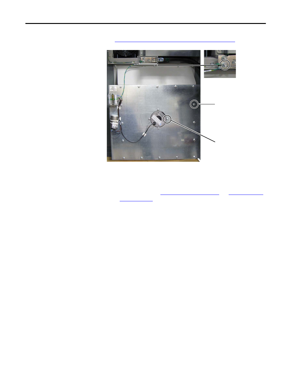
Disconnect TB10 green/
yellow grounding wire.
Heatsink Fan Mounting
Plate Bolts (16)
Heatsink Fan Mounting
Bolts (4)