Maintenance and lubrication instructions – SDC 30-4 ELECTRIC STRIKE User Manual
Page 6
P:\INSTALLATION INST\ELECTRIC STRIKE\INST-30-4.vsd Rev -
01/11 Page 6
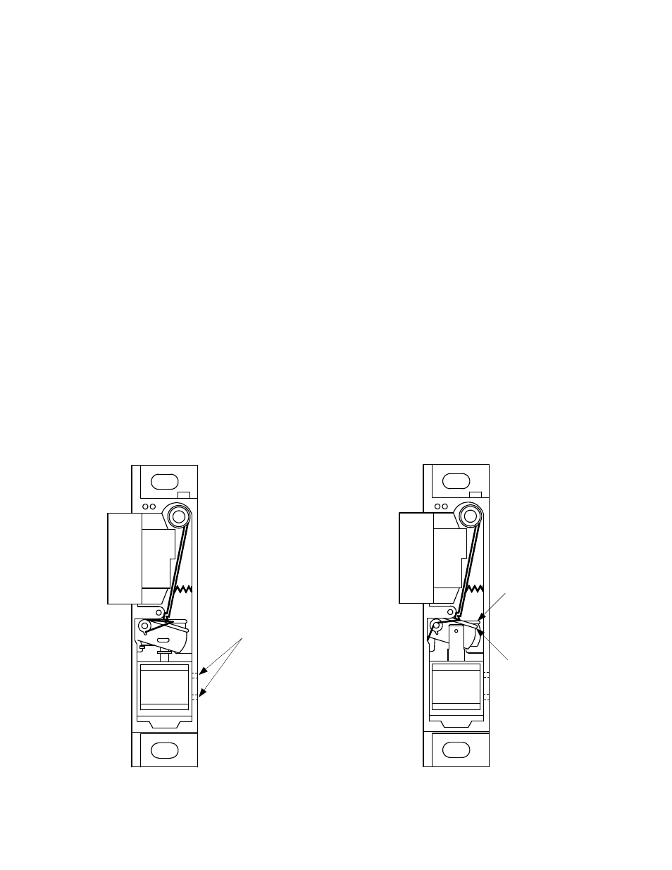
11. Installation and positioning of the solenoid.
NON-FAIL SAFE
1) Install the solenoid and locking cam assembly
2) Install the locking cam spring (with the long leg of the spring on the locking cam and the short leg in the
groove on the case).
3) Before tightening the set screws, energize the solenoid and check the position of the locking cam and locking lever.
4) Adjust the solenoid position to where the locking lever will clear the locking cam and tighten set screws.
FAIL SAFE
1) Install the solenoid and locking cam.
2) Install the locking cam spring (with the long leg of the spring on the locking cam and the short leg in the
groove on the case).
3) Before tightening the set screws, energize the solenoid and check the position of the locking cam.
4) Adjust the position of the solenoid to where it pushes the locking cam into the fully locked position (be careful not to
position the solenoid too high or the solenoid plunger will not seat).
5) De-energize and make sure the locking cam falls to a level to be unlocked. Tighten set screws.
12. Check all screws, tighten if necessary. CAUTION: Do not over tighten the switch screws. Over tightening could damage
the switch.
13. Reinstall the cam spring spacer and the locking lever spacer.
14. Reinstall the upper cover.
15. Reassemble the strike to the face plate.
MAINTENANCE AND LUBRICATION INSTRUCTIONS
Front View
Non Fail Safe
Shown Unlocked
Locked Position
Unlocked Position
Front View
Fail Safe
Shown Locked
Loosen set screws
to position solenoid.
Tighten after position
is set.