Maintenance and lubrication instructions – SDC 30-4 ELECTRIC STRIKE User Manual
Page 5
P:\INSTALLATION INST\ELECTRIC STRIKE\INST-30-4.vsd Rev -
01/11 Page 5
Under normal usage the 30-4 Electric Strike should be cleaned and lubricated once a year to maintain it’s reliability.
In applications with high usage or dirty conditions more frequent service may be necessary. Lubrication points are identified in
the illustration. When servicing the 30-4 Electric Strike, inspect the internal parts for excess wear or breakage and lightly
lubricate per instructions below. Lubricate with lightening grease available from SDC. Never lubricate any strike with oil!
Such lubrication collects dirt and forms an abrasive and sticky compound that may affect the function of the strike.
TO INSPECT AND LUBRICATE THE STRIKE;
1. Remove the strike from the face plate (held on by (2) #12-24 X 3/8” Hex Washer Head Cap SCREWS).
2. Remove the upper cover held on by (2) #4-40 X 3/16” PHMS. Removal of the upper cover should be done slowly because
the locking cam spring may snap out of place. Also, care should be taken to insure that the locking cam spacer and
locking lever spacer are not lost.
3. Remove the cam spring spacer, cam spring and locking lever spacer.
4. Loosen the (2) #6-32 X 1/8” SSSC holding the solenoid, then remove the solenoid and locking cam.
5. Remove the locking lever spring and locking lever. In some versions of the strike, there is a recess in the locking lever and
the case for this spring. In cases with the recess, the locking lever spring must be compressed into the lever before it can
be removed.
6. Lubricate the area in the case where the locking lever and locking cam rest (be careful not to get any lubricant on the
solenoid or switches). Lubricate the cam pin and lever pin.
7. Check the locking angle of the keeper and locking lever for wear. Replace the keeper and/or lever if worn (if the keeper
is disassembled for replacement or adding of a switch, lubricate the keeper pin).
8. Reinstall the locking lever and a new locking lever spring. CAUTION: Make sure the locking lever is placed back into the
recesses of the locking lever and the case.
9. Check the solenoid, plunger and plunger guide for excess wear, dirt, grime or oil. If present, wipe clean.
FAIL SAFE: Remove the retaining ring for inspection of the plunger guide. Reassemble the solenoid and plunger with
a new retaining ring.
NON-FAIL SAFE: Lubricate the bottom edge of the locking cam (contact point of the solenoid plunger).
10. NON-FAIL SAFE: Lubricate the slot in the locking cam
FAIL SAFE: Lubricate the bottom edge of the locking cam (contact point of the solenoid plunger).
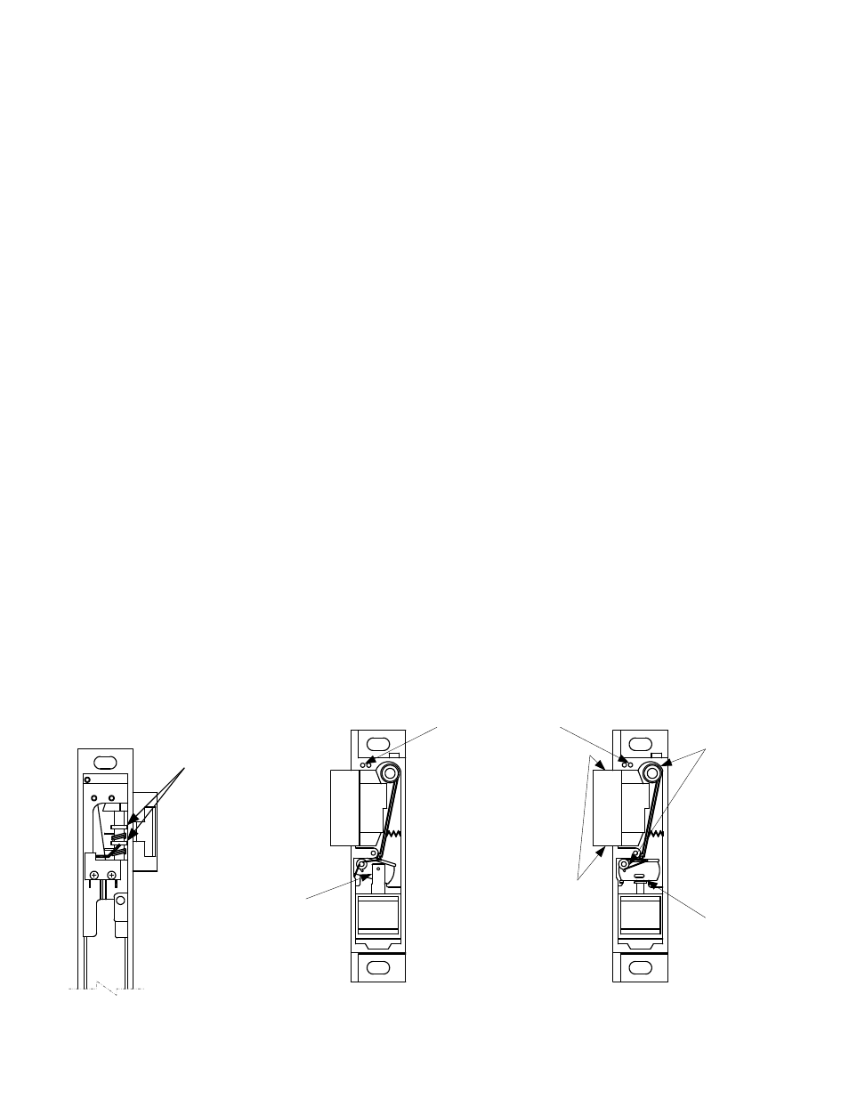
MAINTENANCE AND LUBRICATION INSTRUCTIONS
Lightening grease
hubs where they
contact keeper
Rear view shown
with LCBM switch
Lightening grease
keeper pin
before assembly
Lightening grease
sides of keeper
before assembly
Lightening grease
cam slot and both
cam surfaces
between plunger
Front View
Non Fail Safe
Shown Unlocked
Front view
Fail Safe
Shown Locked
Lightening grease
pins and bottom
of case
Lightening grease
bottom of cam
and plunger pin