4 series electric strike wiring diagrams, Attachment of new rectifier, Attachment of old rectifier – SDC 30-4 ELECTRIC STRIKE User Manual
Page 3: Push button switch conditions, N/c n/o lock n/c n/o unlock
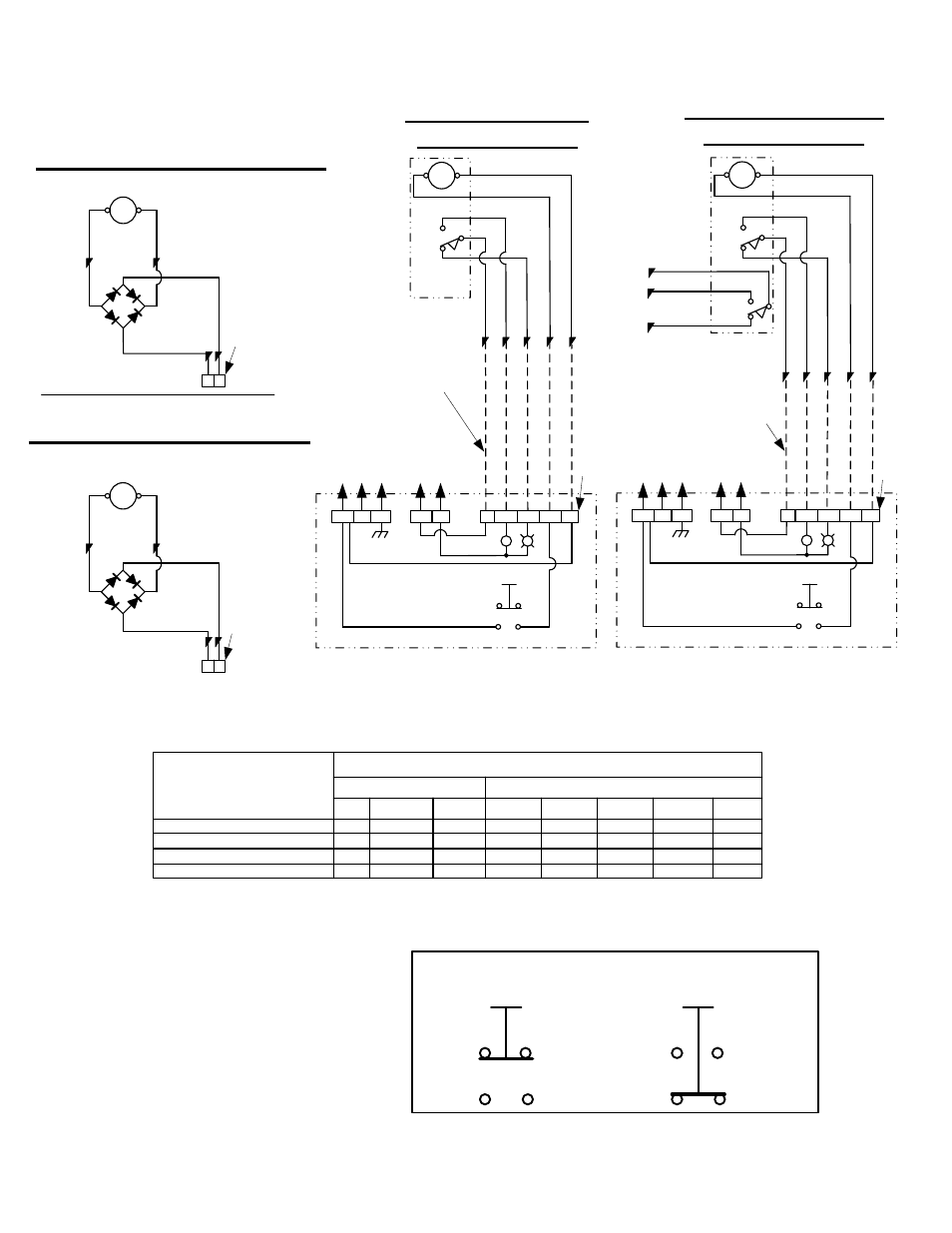
30-4 SERIES ELECTRIC STRIKE WIRING DIAGRAMS
Notice:
Wiring subject to change without
prior notice. Not responsible for
controls furnished by others.
Attachment of New Rectifier
(Required when supplying AC power
to a unit with a DC solenoid)
DC solenoid
B
la
c
k
/Y
e
llo
w
T
ra
c
e
r
Brown
Terminal
Strip
Brown
B
la
c
k
/Y
e
llo
w
Bridge
Rectifier
Rating:
2 Amps at ANY
Solenoid Voltage
Y
Y
e
llo
w
Y
e
llo
w
-
*
Attachment of Old Rectifier
(Required when supplying AC power
to a unit with a DC solenoid)
DC solenoid
B
la
c
k
/Y
e
llo
w
T
ra
c
e
r
Yellow
Terminal
Strip
Yellow
B
la
c
k
Bridge
Rectifier
Rating:
2 Amps at ANY
Solenoid Voltage
Y
*
R
e
d
Y
e
llo
w
B
la
c
k
R
e
d
B
lu
e
Y
e
llo
w
*
9
3
6
1
4
N/O
N/C
C
Dotted Lines Represent
Field wires by others
+
-
Y
*
B
R
+
-
GND
R
G
Push
Button
N/C
N/O
Typical Control
Schematic for
Reference only
Lock Cam/Bolt
Monitor Switch
(Long Arm)
Control
Power
Indication
Power
Unlocked When Energized
Terminal
Strip
B
la
c
k
R
e
d
B
lu
e
Y
e
llo
w
*
9
3
6
1
4
N/O
N/C
C
Dotted Lines Represent
Field wires by others
+
-
Y
*
B
R
+
-
GND
R
G
Push
Button
N/C
N/O
Typical Control
Schematic for
Reference only
Lock Cam/Bolt
Monitor Switch
(Long Arm)
Control
Power
Indication
Power
Unlocked When Energized
Terminal
Strip
Push Button Switch Conditions
N/C
N/O
Lock
N/C
N/O
Unlock
P:\INSTALLATION INST\ELECTRIC STRIKE\INST-30-4.vsd Rev -
01/11 Page 3
Solenoid
Solenoid
30-4 Series LCBM
Wiring Diagram
30-4 Series LCBMA
Wiring Diagram
C
N/O
N/C
ORANGE
BROWN
PURPLE
Auxiliary
Switch
(LBM)
7
5
8
Electrical Ratings for
ALL 30-4
Electric Strike Solenoids
Resistance in OHMS +/- 10% 6.2
23.5
500
6.2
23.5
96.0
380
1200
Watts Seated
5.4
5.8
6.3
5.8
6.1
6.0
6.1
6.3
Amps Seated
.45
.24
.06
.97
.51
.25
.13
.06
Amps Inrush
1.33
.69
.16
N/A
N/A
N/A
N/A
N/A
12
24
120
6
12
24
48
120
AC
DC
VOLTAGE