4 electric strike wiring diagrams, Fail safe controls, Optional dbs switch (not available with lcbma) – SDC 30-4 ELECTRIC STRIKE User Manual
Page 4: 4 lbm wiring diagram, 4 lcm wiring diagram, Field receptacle
P:\INSTALLATION INST\ELECTRIC STRIKE\INST-30-4.vsd Rev -
01/11 Page 4
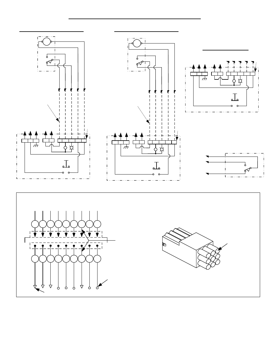
30-4 ELECTRIC STRIKE WIRING DIAGRAMS
+
-
Y
*
B
R
+
-
GND
R
G
Push
Button
N/C
N/O
Typical Control
Schematic for
Reference only
Control
Power
Indication
Power
Locked When Energized
(Fail Safe) all 300 Strikes
Terminal
Strip
Fail Safe Controls
Grey
Orange
Purple
7
5
8
Auxiliary
Contacts
Optional DBS Switch
(not available with LCBMA)
Door shown closed and locked.
Dead Bolt Extended into Face Plate
NOTES:
1) = Wires color code
6 thru 120 VDC Yellow/Black Tracer
12 & 24 VAC-Grey
120 VAC-White
2) Unused wires to be individually isolated with a wire nut or equal.
3) Numbered field connections refer to pin location in field receptacle.
*
B
ro
w
n
O
ra
n
g
e
P
u
rp
le
Y
e
llo
w
*
7
5
8
1
4
N/O
N/C
C
Dotted Lines Represent
Field wires by others
+
-
Y
*
B
R
+
-
GND
R
G
Push
Button
N/C
N/O
Typical Control
Schematic for
Reference only
Latch Bolt
Monitor Switch
Control
Power
Indication
Power
Unlocked When Energized
Terminal
Strip
30-4 LBM wiring diagram
Solenoid
30-4 LCM wiring diagram
B
la
c
k
R
e
d
B
lu
e
Y
e
llo
w
*
9
3
6
1
4
N/O
N/C
C
Dotted Lines Represent
Field wires by others
+
-
Y
*
B
R
+
-
GND
R
G
Push
Button
N/C
N/O
Typical Control
Schematic for
Reference only
Latch Bolt
Monitor Switch
Control
Power
Indication
Power
Unlocked When Energized
Terminal
Strip
Solenoid
1
2
3
6
5
4
9
8
7
Optional 9-Pin Field Wiring Conn.
7 5 8 9 3 6 2 1
*
Strike Wires
7 5 8 9 3 6 2 1 4
G
R
Y
o
r
B
R
N
O
R
G
P
U
R
B
L
K
R
E
D
B
L
U
Y
E
L
Y
E
L
W
H
T
Pin #2
Not Used
Field
Connector
Aux Contacts
Field
Receptacle
Pin
Location
Installation Must Be Properly Grounded
Per National Electrical Code Article 250