3 digital inputs setup menu – SATEC PM296 User Manual
Page 33
Chapter 4 Setup Menus
25
4.3 Digital Inputs Setup Menu
This menu is used to set up the 12 digital inputs provided by the PM296/RPM096.
Each digital input can be allocated as:
- a status input to monitor external contact status, or
- a pulse input to sense pulses provided by an external source. One of these can be
configured to receive an external synchronization pulse indicating the beginning of a new
demand interval for power demand measurements.
A pulse input can also be configured to receive time synchronization pulses to
provide synchronization of the instrument clock with a precise external time
source. Time synchronization pulses can follow in intervals of one minute
multiples aligned at 00 seconds. Receipt of the external pulse adjusts the RTC at
the nearest round minute. Whenever a precise external demand synchronization
source is used, the same input that is allocated for this pulse can be configured
as a time synchronization input.
An input allocated for the external synchronization pulse will be automatically configured as
a pulse input. Status inputs need not to be explicitly allocated in your instrument. All digital
inputs except those you have allocated as pulse inputs are automatically configured as
status inputs.
Pulse inputs
External demand
synchronization input
Time synchronization
input
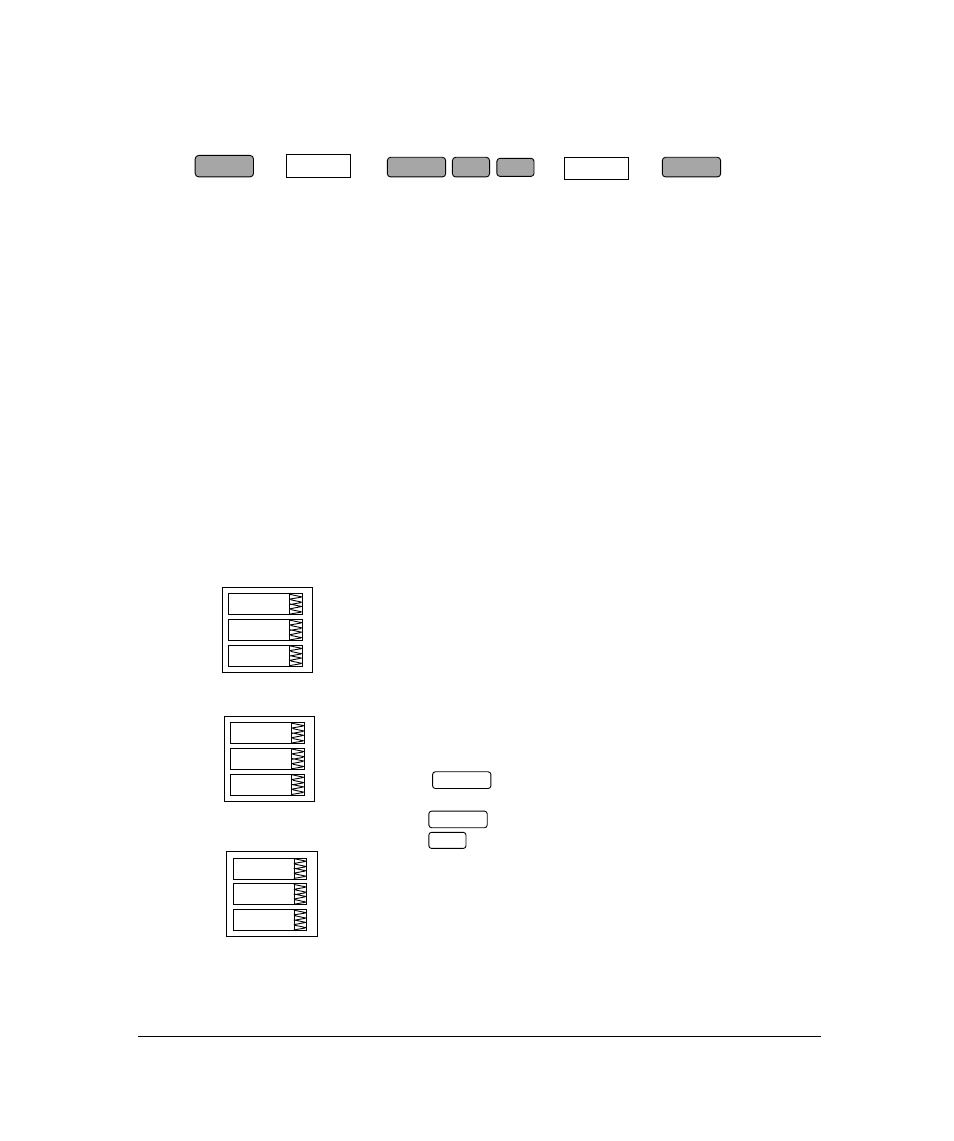
To select and view inputs allocation:
Scroll through the inputs allocation sub-menus in the upper
window using the up/down arrow keys. The sub-menus are
shown at left. For each allocation group, two sub-menus are
used: the first showing inputs #1 through #8 and the second -
inputs #9 through #12.
Digital inputs are numbered from left to right. “0” indicates “not
allocated”; “1” indicates “allocated”. Each digital input is set
separately.
To change the digital input allocation:
Press to activate the middle window.
Use the up/down arrow keys to set the input allocation status.
Press to store your new inputs allocation.
Press to leave the allocation unchanged or to quit the
menu.
E.Sn.1
0.0.0.0
0.1.0.0
P.In.1
0.0.0.0
0.1.0.0
ESC
t.Sn.9
0.0.0.1
NOTE
Digital inputs configured as status inputs can be monitored via the
Status Information Menu
(see Chapter 6) and communications. The
pulses being received via pulse inputs can be directed to one of the
four pulse counters (see Section 4.4) and, at the same time, to
either of the TOU system energy registers.
ENTER
SELECT
SELECT
CHG
dinP
ENTER
ENTER