SATEC EM920 Operation Manual User Manual
Page 80
Chapter 5 Configuring the EM920
General Meter Setup
80
EM920 Power Quality and Revenue Meter
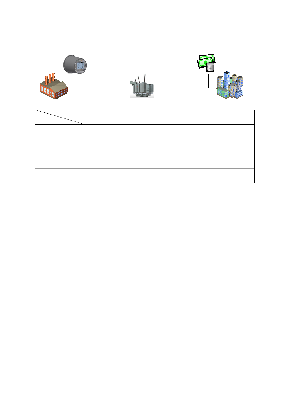
metering and billing points. Use the picture and table
below to check your settings.
Billing Point
Metering Point
Supply side,
far end
Supply side,
transformer end
Load side,
transformer end
Load side,
far end
Supply side,
far end
-Supply line losses
-Supply line losses
-Transformer losses
-Supply line losses
-Transformer losses
-Load line losses
Supply side,
transformer end
+Supply line losses
-Transformer losses -Transformer losses
-Load line losses
Load side,
transformer end
+Supply line losses
+Transformer losses
+Transformer losses
-Load line losses
Load side,
far end
+Supply line losses
+Transformer losses
+Load line losses
+Transformer losses
+Load line losses
+Load line losses
2. Select the number of metering elements depending on
the wiring mode set in the meter. It is not a critical
parameter and the actual losses will not be affected by
this setting.
3. Specify the power transformer data. It is normally
taken from the transformer nameplate and
transformer datasheet. All transformer data is given
for a 3-phase system.
4. If the supply-side or/and load-side power line losses
are to be included in compensation, specify the length
of power lines and their resistance and reactance per
mile or km. To change the length units, select Options
from the Tools menu, click on the Preferences tab, and
then check the preferred distance units.
5. After all data is specified, click on the Calculate %Loss
Constants button to update the loss constants.
6. Select Enable in the Loss Compensation Enabled box to
enable loss compensation in the meter.
7. Send your new setup to the meter.
NOTE
You can also enable and disable loss compensation via the
front display (see
Device Options and Mode Control
Supply line
Load line
Power transformer
Far end
Far end
Transformer end
Transformer end
Metering point
Billing point