SATEC EM920 Operation Manual User Manual
Page 79
Chapter 5 Configuring the EM920
General Meter Setup
EM920 Power Quality and Revenue Meter
79
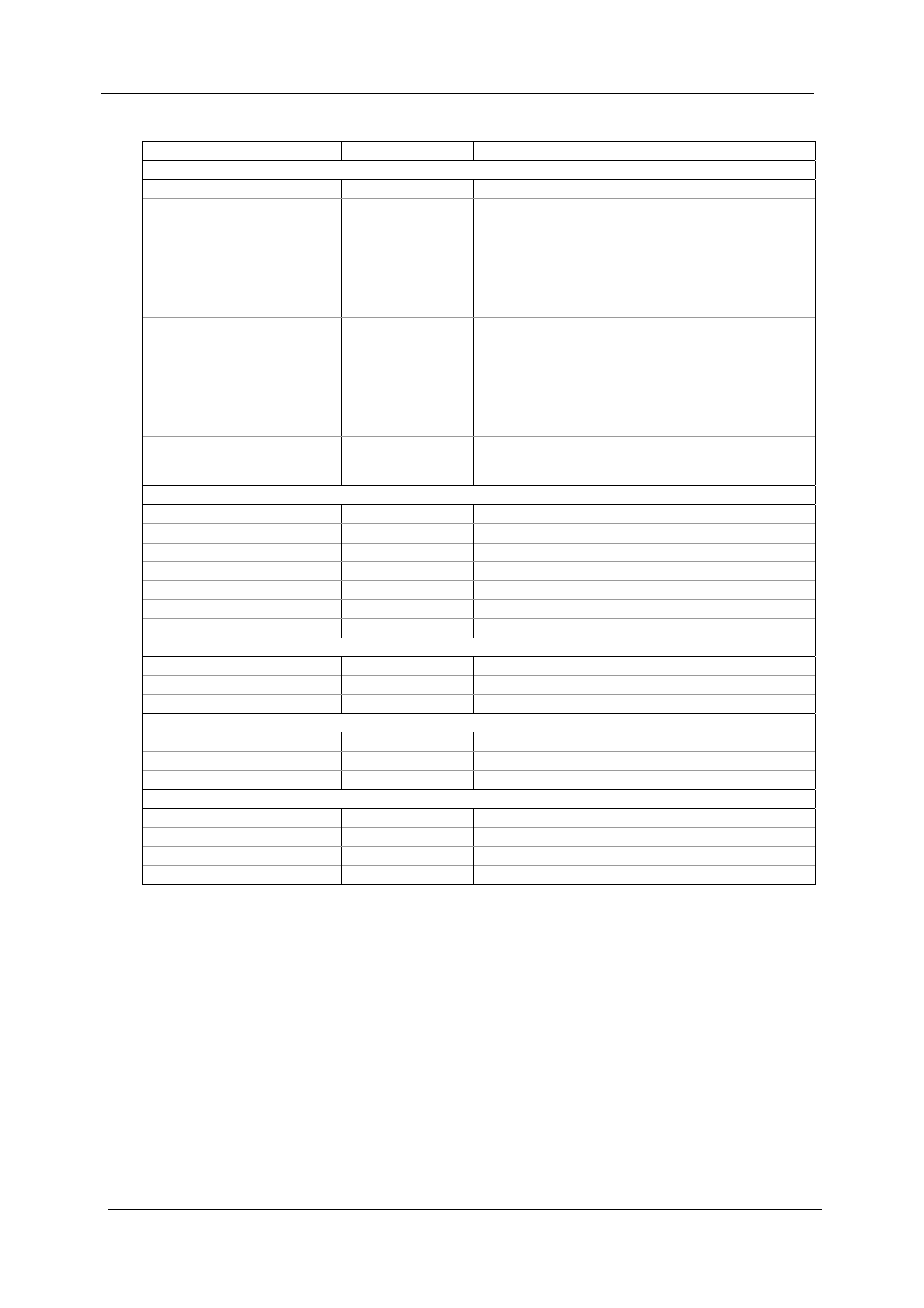
The available options are described in the following table.
Parameter Options
Description
Metering and Location
Loss Compensation Enabled
Disabled, Enabled
Enables/disables loss compensation
Metering Point Location
Supply side, far
end,
Supply side,
transformer end,
Load side,
transformer end,
Load side, far end
Defines the location of the meter:
far end – near the supply source or near the load,
transformer end – near the power transformer.
Billing Point Location
Supply side, far
end,
Supply side,
transformer end,
Load side,
transformer end,
Load side, far end
Defines the location of the billing point:
far end – near the supply source or near the load,
transformer end – near the power transformer.
Number of Metering Elements 2 (Open Delta)
3 (WYE)
Defines the number of metering elements in the
meter depending on the wiring mode. Select 2 for
3OP2/3OP2, and 3 for 4LN3/4LL3 wiring modes.
Power Transformer Data
Primary Rated Voltage, V
Primary rated voltage of the power transformer
Secondary Rated Voltage, V
Secondary rated voltage of the power transformer
Rated Power, kVA
Rated transformer power
No-load Iron Watt Loss
Watt losses at rated voltage due to iron
Full-load Copper Watt Loss
Watt losses at rated voltage due to copper
Percent Excitation Current
Transformer percent exciting current
Percent Impedance
Transformer percent impedance
Supply-side Power Line Data
Length, miles
Power line length, in miles or km
Resistance, Ohm/mile
Power line resistance, in Ohm/mile or Ohm/km
Reactance, Ohm/mile
Power line inductance, in Ohm/mile or Ohm/km
Load-side Power Line Data
Length, miles
Power line length, in miles or km
Resistance, Ohm/mile
Power line resistance, in Ohm/mile or Ohm/km
Reactance, Ohm/mile
Power line inductance, in Ohm/mile or Ohm/km
%Loss Constants
Iron Watt Losses, %LWFe
Percent watt losses due to iron
Copper Watt Losses, %LWCu
Percent watt losses due to copper
Iron VAR Losses, %LVFe
Percent var losses due to iron
Copper VAR Losses, %LVCu
Percent var losses due to copper
The EM920 uses pre-calculated loss constants for correcting
meter readings. All calculations are performed by Pas using
transformer and power line data, and then the resulting loss
constants are downloaded to the meter. If power line losses
are included in compensation, they are added to the loss
constants.
For more information on the loss calculation techniques, see
the Handbook for Electricity Metering, 10-th edition, by the
Edison Electric Institute.
To configure loss constants in the meter:
1. Specify the locations of the meter and a point of
billing. The losses will be added to, or subtracted from
the measured power depending on the locations of the