SATEC C192PF8-RPR User Manual
Page 45
Chapter 4 Setup Menus
40
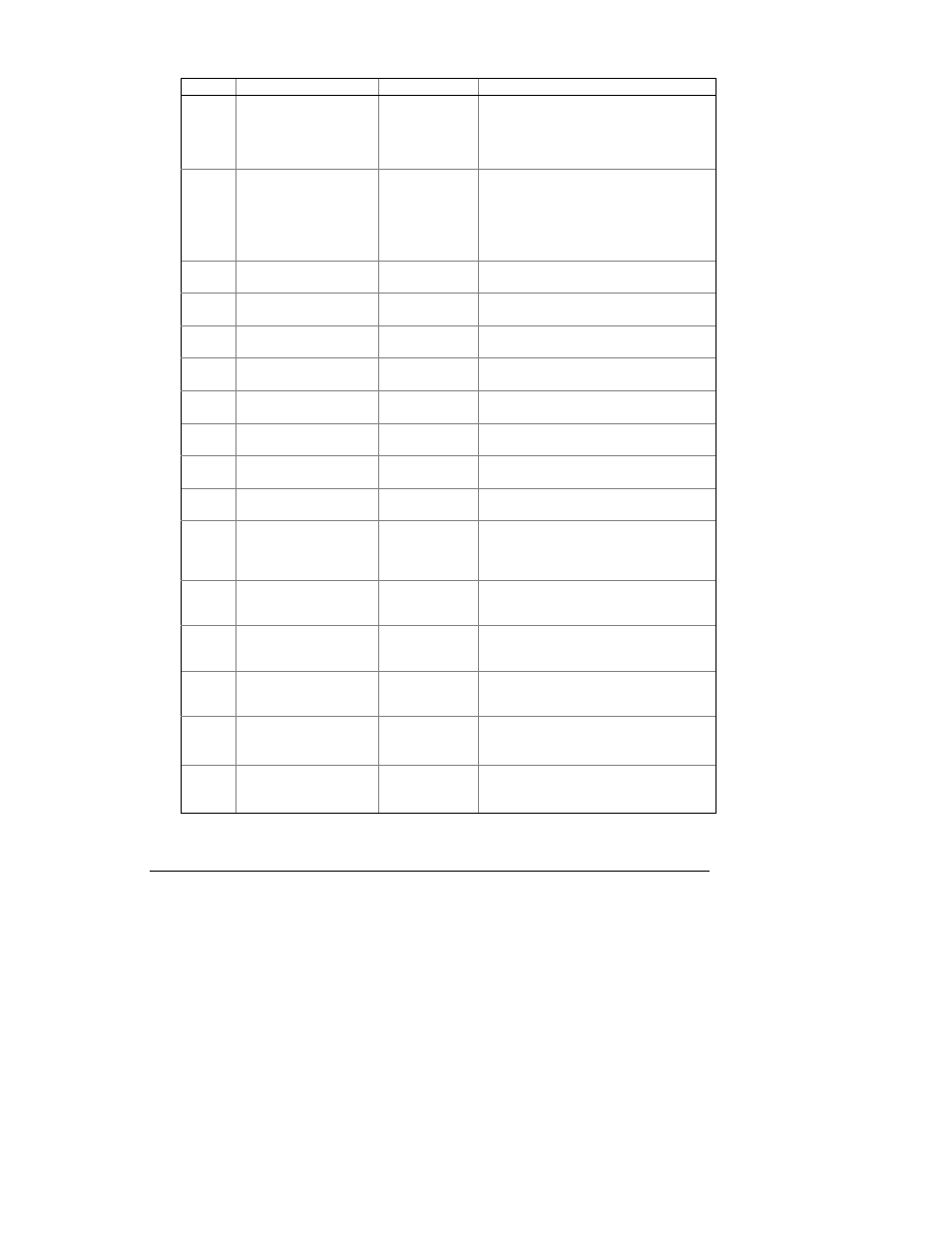
Code Parameter
Options
Description
SP1-2
∗
Two target setpoint ranges are defined by
setpoints SP1 and SP2 (generally, to
differentiate between day and night
operations). The active setpoint range is
selected through a digital (status) input.
U.CAP Nominal voltage of the
capacitor banks
0
∗
,
1V to 999V,
0.01kV to
99.99kV
1V to 999V if PT RATIO = 1
0.01kV to 99.99 kV if PT RATIO > 1
0 = disable automatic adjustment of the
capacitor bank powers to the measured
line voltage (assuming that those have
been adjusted manually)
L.PF1
Low target PF1 (in PFC
mode)
0.500 to -0.500
Low target power factor for setpoint SP1
H.PF1
High target PF1 (in PFC
mode)
0.500 to -0.500
High target power factor for setpoint SP1
L.PF2 Low target PF2 (in PFC
mode)
0.500 to -0.500
Low target power factor for setpoint SP2
H.PF2 High target PF2 (in PFC
mode)
0.500 to -0.500
High target power factor for setpoint SP2
L.rE1
Low target kvar 1 (in
RPR mode)
-10000 to 10000
(-750)
Low target kvar for setpoint SP1
H.rE1
High target kvar 1 (in
RPR mode)
-10000 to 10000
(1200)
High target kvar for setpoint SP1
L.rE2 Low target kvar 2 (in
RPR mode)
-10000 to 10000
(-750)
Low target kvar for setpoint SP2
H.rE2 High target kvar 2 (in
RPR mode)
-10000 to 10000
(1200)
High target kvar for setpoint SP2
OP.d
Setpoint operate delay,
sec
1 to 3600 s (3
∗
) The amount of time that the power factor
must be continuously outside the setpoint
range in order to run the automatic power
factor correction
On.d
Switch-on time
(connection interval), sec
3 to 3600 s
(600
∗
)
The amount of idling time after a capacitor
bank switches in, when further switching
operations are prohibited
OFF.d
Switch-off time
(disconnection interval),
sec
3 to 3600 s
(600
∗
)
The amount of idling time after a capacitor
bank switches out, when further switching
operations are prohibited
rEc.d
Re-connection
(discharge) time, sec
5 to 3600 s
(300
∗
)
The capacitor bank reclose delay to allow
the capacitors to discharge after
disconnecting
CAP1
Size of the capacitor
bank #1, kvar
On, nonE,
1 to 10000 kvar
(1500
∗
)
Power rating of the capacitor bank.
nonE = not used,
On = permanently switched in
CAP2
Size of the capacitor
bank #2, kvar
On, nonE,
1 to 10000 kvar
(1500
∗
)
Power rating of the capacitor bank.
nonE = not used,
On = permanently switched in