SATEC C192PF8-RPR User Manual
Page 34
Chapter 4 Setup Menus
29
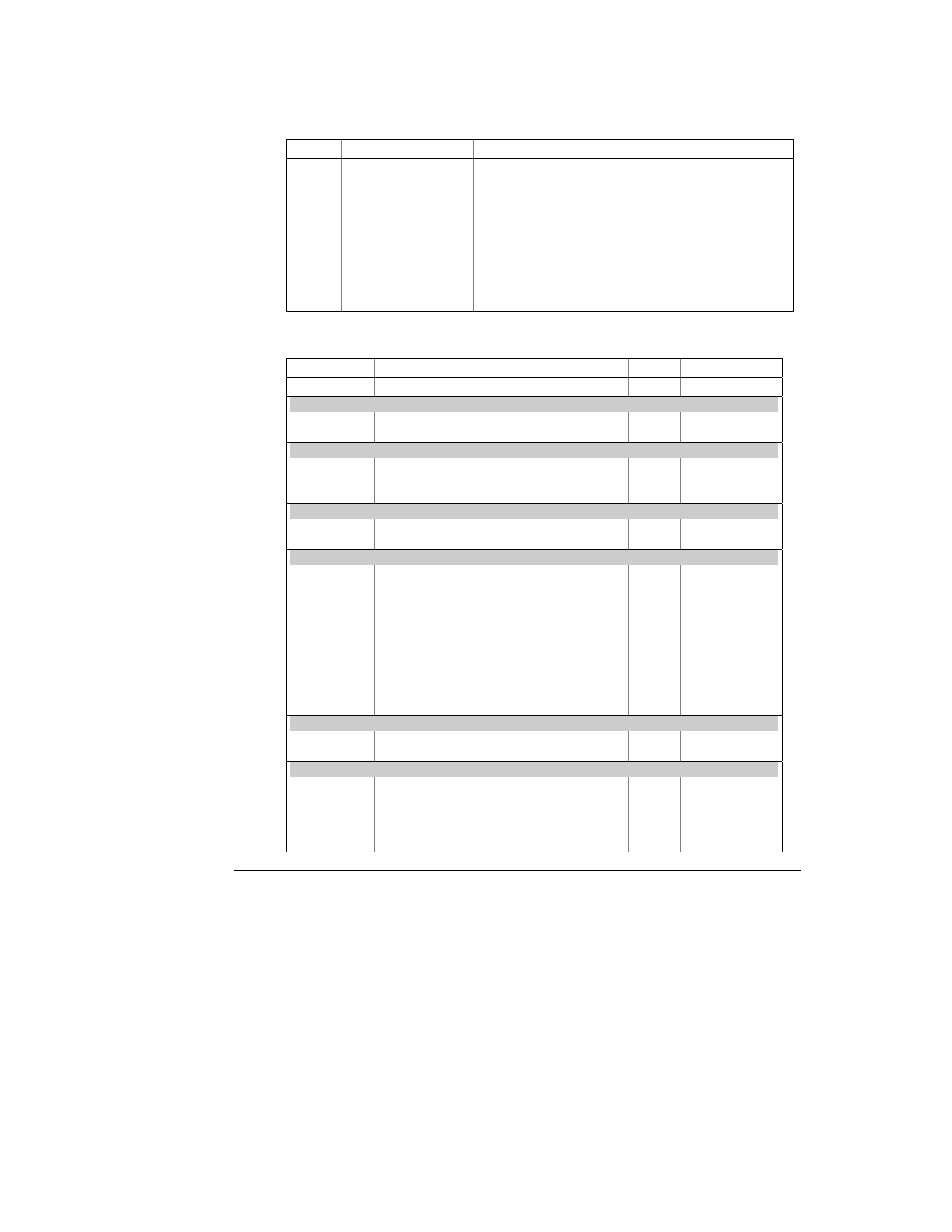
Table 4-6 Setpoint Setup Options (middle window)
Code Option
Description
trig
Trigger parameter
The measurement parameter or signal to be monitored
by the setpoint.
On
Operate limit
The threshold at which the setpoint becomes operative.
OFF
Release limit
The threshold at which the setpoint is released (becomes
inoperative).
On d
Operate delay
The time delay (0.1 second resolution) before operation
when the operate condition is fulfilled.
OFF d
Release delay
The time delay (0.1 second resolution) before release
when the release condition is fulfilled.
Act
Setpoint action
The action performed when the setpoint is operative.
Table 4-7 Setpoint Triggers (lower window, when middle window is triG)
Code Parameter
Unit
Range
nonE
Setpoint
disabled
Status Input
St.On
Status input ON
St.OFF
Status input OFF
Fault Triggers
FAult
Device Fault (diagnostics error)
no-U
No-Volt
UncoP
Uncompensated reactive power
Phase Reversal
POS.ro.
Positive phase rotation reversal
NEG.ro.
Negative phase rotation reversal
Real-time Values on any Phase
r. Hi. U
High voltage
V
0 to Vmax
r. Hi. LU
High L-L voltage
V
0 to Vmax
r. Lo. U
Low voltage
V
0 to Vmax
r. Lo. LU
Low L-L voltage
V
0 to Vmax
r. Hi. C
High current
A
0 to Imax
r. Lo. C
Low current
A
0 to Imax
r. thd.U
High voltage THD
%
0 to 999.9
r. thd.C
High current THD
%
0 to 999.9
r. HFc.C
High K-factor
%
1.0 to 999.9
r. tdd.C
High current TDD
%
0 to 100.0
Real-time Auxiliary Measurements
r. Hi.Fr
High frequency
Hz
0 to 100.00
r. Lo.Fr
Low frequency
Hz
0 to 100.00
Average Values per Phase
A. Hi.C1
High current L1
A
0 to Imax
A. Hi.C2
High current L2
A
0 to Imax
A. Hi.C3
High current L3
A
0 to Imax
A. Lo.C1
Low current L1
A
0 to Imax
A. Lo.C2
Low current L2
A
0 to Imax