SATEC C192PF8-RPR User Manual
Page 35
Chapter 4 Setup Menus
30
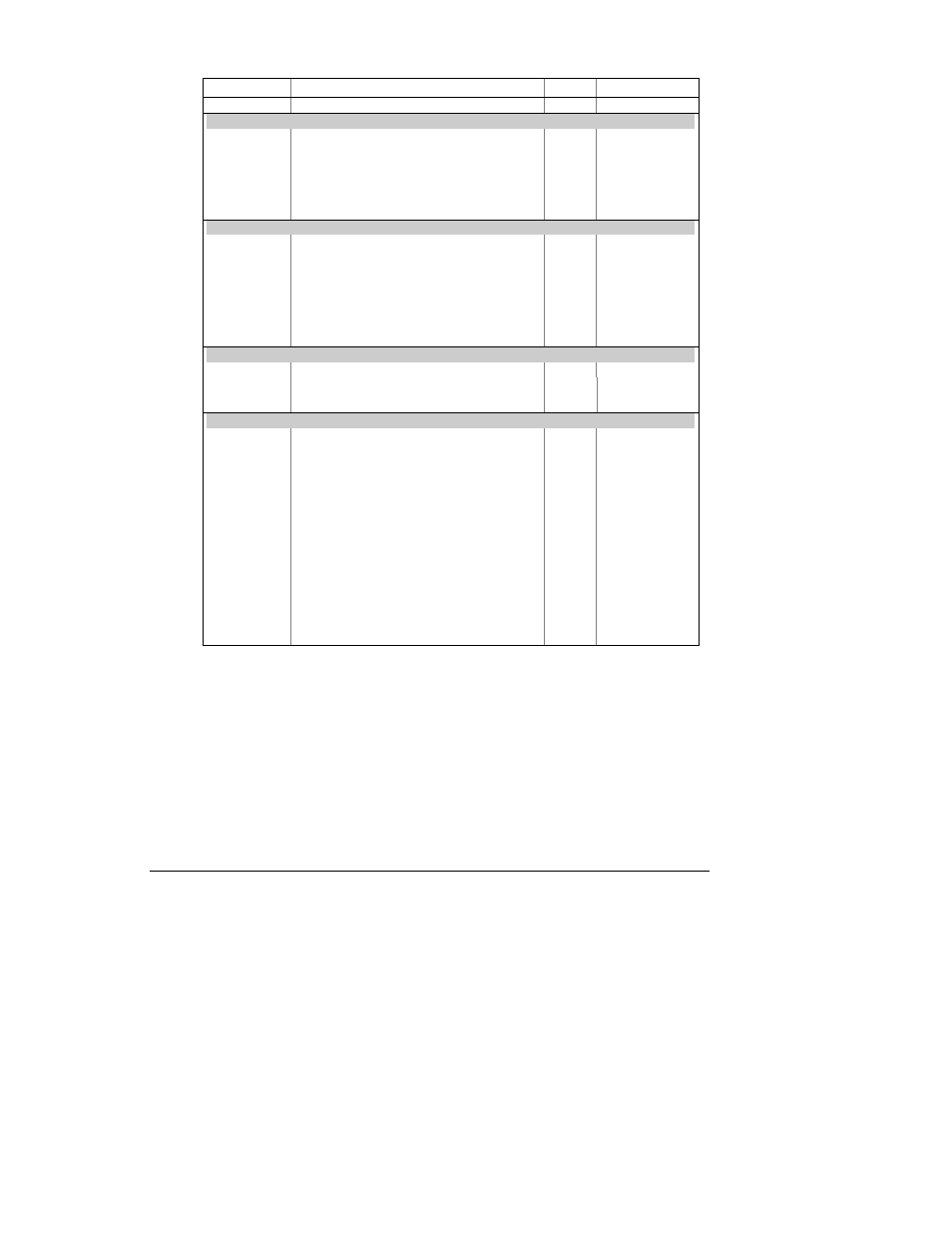
Code Parameter
Unit
Range
A. Lo.C3
Low current L3
A
0 to Imax
Average Values on any Phase
A. Hi. U
High voltage
V
0 to Vmax
A. Hi. LU
High L-L voltage
V
0 to Vmax
A. Lo. U
Low voltage
V
0 to Vmax
A. Lo. LU
Low L-L voltage
V
0 to Vmax
A. Hi. C
High current
A
0 to Imax
A. Lo. C
Low current
A
0 to Imax
Average Total Values
A. Hi.P.i
High total kW import (positive)
kW
0 to Pmax
A. Hi.P.E
High total kW export (negative)
kW
0 to Pmax
A. Hi.q.i
High total kvar import (positive)
kvar
0 to Pmax
A. Hi.q.E
High total kvar export (negative)
kvar
0 to Pmax
A. Hi. S
High total kVA
kVA
0 to Pmax
A. PF.LG
Low total PF Lag
0 to 1.000
A. PF.Ld
Low total PF Lead
0 to 1.000
Average Auxiliary Measurements
Ar neU.C
High neutral current
A
0 to Imax
Ar Hi.Fr
High frequency
Hz
0 to 100.00
Ar Lo.Fr
Low frequency
Hz
0 to 100.00
Present Demands
Hi d.U1
High volt demand L1
V
0 to Vmax
Hi d.U2
High volt demand L2
V
0 to Vmax
Hi d.U3
High volt demand L3
V
0 to Vmax
Hi d.C1
High ampere demand L1
A
0 to Imax
Hi d.C2
High ampere demand L2
A
0 to Imax
Hi d.C3
High ampere demand L3
A
0 to Imax
Hi d.P
High block interval kW demand
kW
0 to Pmax
Hi d.S
High block interval kVA demand
kVA
0 to Pmax
Hi Sd.P
High sliding window kW demand
kW
0 to Pmax
Hi Sd.S
High sliding window kVA demand
kVA
0 to Pmax
Hi Ad.P
High accumulated kW demand
kW
0 to Pmax
Hi Ad.S
High accumulated kVA demand
kVA
0 to Pmax
Hi Pd.P
High predicted sliding window kW demand kW
0 to Pmax
Hi Pd.S
High predicted sliding window kVA demand kVA
0 to Pmax
For parameter limits, see notes to Table 4-4.
The setpoint is operated when the actual phase sequence does not match the indicated
normal phase rotation.
The actual frequency range is 45.00 - 65.00 Hz.
When the 4LN3 or 3LN3 wiring mode is selected, the voltages will be line-to-neutral; for
any other wiring mode, they will be line-to-line voltages.
The Device Fault trigger is active when the self-diagnostics test detects a critical
(unrecoverable) error. This could happen when a corrupted configuration setup or
incompatible setup setting is detected. In this event, the device will reset the corrupted
setup to default. The trigger is cleared when the setup is rewritten or device diagnostics
is cleared either through the Status Information Menu (see Section 7.1), or through
communications. When a non-critical error is detected, the device will only set a
corresponding fault bit in the self-check diagnostics register and restart operations.