Recommended modbus wiring, Termination jumper, Modbus master – RKI Instruments Beacon 410 User Manual
Page 59
Beacon 410 Gas Monitor Operator’s Manual
Wiring the Beacon 410 in a Modbus System • 55
Recommended Modbus Wiring
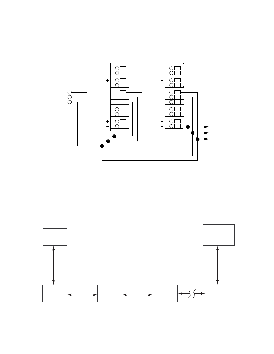
The recommended Modbus wiring for the Beacon 410 is illustrated in Figure 14 below.
Figure 14: Recommended Modbus Wiring
Termination Jumper
The Beacon 410 includes a 2-pin termination header (see Figure 1) that may need to be
installed when the Beacon 410 is used in a Modbus system. Every Beacon 410 is supplied
with a termination jumper (a jumper block) installed onto this header. If the Beacon 410 is
not used in a Modbus system, this jumper has no function. When the Beacon 410 is
installed in a Modbus system, this jumper must be installed in a Beacon 410 that is at the
end of a Modbus line. Any Beacon 410 in a Modbus system that is not at the end of a line
must have the termination jumper removed (see Figure 15 & Figure 16 below).
Figure 15: Multiple Beacon 410s in a Daisy Chain Configuration
D1
Common
Beacon 410
Controller Terminal Strip
2
4
V
BAT
T
E
X
T
D
C
DP SW
Beacon 410
Controller Terminal Strip
DP SW
A
B
Modbus
Controller
2
4
V
BAT
T
E
X
T
D
C
DP SW
DP SW
A
B
ALARM
RESET
AL
A
R
M
B
U
ZZE
R
To Additional
Beacon 410s
ALARM
RESET
AL
A
R
M
B
U
ZZE
R
R
S
-485
C
D0
Input
Terminals
R
S
-485
C
Modbus
Master
Beacon 410
Termination
Jumper
Installed
Beacon 410
Termination
Jumper
Not Installed
Beacon 410
Termination
Jumper
Not Installed
Beacon 410
Termination
Jumper
Not Installed
Beacon 410
Termination
Jumper
Not Installed
ID = 32
ID = 31
ID = 30
ID = 29
ID = 1
Up to 32 Beacon 410s can be connected without a repeater.
RS-485
RS-485