Wiring the beacon 410 gas monitor – RKI Instruments Beacon 410 User Manual
Page 19
Beacon 410 Gas Monitor Operator’s Manual
Wiring the Beacon 410 Gas Monitor • 15
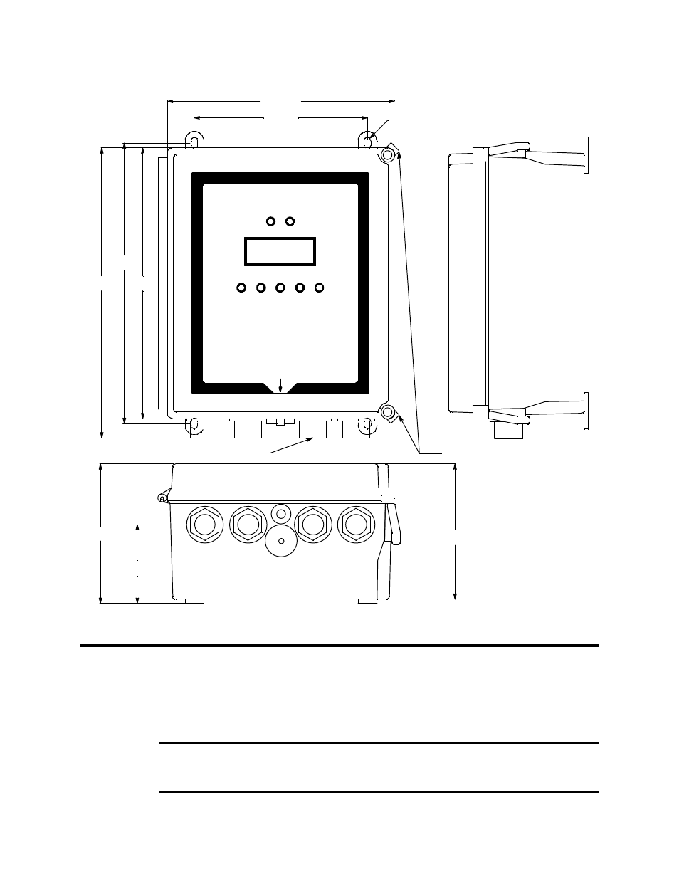
Figure 7: Beacon 410 Gas Monitor Outline and Mounting Dimensions
Wiring the Beacon 410 Gas Monitor
This section describes procedures to connect the AC power source, DC power source,
Modbus wiring (refer to “Wiring the Beacon 410 in a Modbus System” on page 54),
external alarms, recording devices, and detector heads. See Figure 8 on page 16 for a
general diagram of all external wiring to the Beacon 410.
WARNING:
Make all connections to the Beacon 410 before you plug in or turn on the AC or
DC power source. Before you make any wiring adjustments, always verify that all
power sources are not live.
Ø .31 x .50 slot, 4X
Door Latches
13.39
12.94
12.50
3/4" Conduit Hubs, 4X
6.43
3.63
8.00
6.25
10.50
- Eagle Series (89 pages)
- Eagle Series (66 pages)
- 01 Series Manual (33 pages)
- 01 Series Quik Start (2 pages)
- OX-94 (13 pages)
- FP-3 (16 pages)
- GasWatch 1 (18 pages)
- GasWatch 2 Manual (37 pages)
- GasWatch 2 Quik Start (2 pages)
- GP-01 (34 pages)
- GP-01 with self resetting alarms (33 pages)
- GP-204 (7 pages)
- NP-204 (13 pages)
- RI-215A (24 pages)
- SC-01 (45 pages)
- SC-01 (68 pages)
- Data Cal 2000 (88 pages)
- EAGLE 2 Manual (309 pages)
- Eagle 2 Quik Start (2 pages)
- GX-94 (3 pages)
- GX-94 (52 pages)
- SDM-E2 (89 pages)
- SDM-E2 (224 pages)
- Eagle 1 Manual (89 pages)
- Eagle 1 Quik Start (2 pages)
- Inert Gas Testing Eagle with Two Pumps (66 pages)
- Gas Tracer (234 pages)
- Gas Tracer 10,000 ppm (120 pages)
- GX-2001 Manual (45 pages)
- GX-2001 Quik Start (2 pages)
- GX-2001 Canadian Version (43 pages)
- GX-2003 Manual (94 pages)
- GX-2003 Quik Start (2 pages)
- GX-2009 Manual (73 pages)
- GX-2009 Quik Start (2 pages)
- GX-2009 Supplement (2 pages)
- GX-2012 Manual (185 pages)
- GX-82 (22 pages)
- GX-82A (43 pages)
- GX-86 (22 pages)
- GX-86A (39 pages)
- GX-8000(PT0-098) (52 pages)
- GX-8000(H4-0050) (23 pages)
- RX-516 (36 pages)
- GX-2009 (2 pages)