RKI Instruments Beacon 410 User Manual
Page 25
Beacon 410 Gas Monitor Operator’s Manual
Wiring the Beacon 410 Gas Monitor • 21
detector head to a controller.
4.
Install an appropriately rated cable bushing or conduit in an unused conduit hub on
the bottom of the Beacon 410 housing.
5.
Route the wires in conduit or shielded cable from the detector head through the
selected conduit hub into the Beacon 410. See Table 4 below for wire size and
distance guidelines.
6.
Unshielded twisted pair cable in conduit or shielded twisted pair cable is
recommended for all the direct connect detector heads. For the LEL detector, pair and
twist the R & B wires and the W & G wires. Shielded cable or wires in conduit are
recommended for the 2-wire and 3-wire 4 - 20 mA transmitters.
7.
Connect the wires from the detector head to the appropriate detector/transmitter
terminals on the appropriate channel. See the detector head operator’s manual and
the Beacon 410 Detector Head Specification Sheet for detector head connections to
the Beacon 410. If shielded cable is used, leave the cable shield’s drain wire
disconnected and insulated at the detector head and connect the cable shield’s drain
wire at the Beacon 410 to the ground stud on the main PCB.
CAUTION: Do not route power and detector head wiring through the same conduit hub.
The power wiring may disrupt the transmission of the detector head’s signal
to the Beacon 410.
Connecting User-Supplied 4 - 20 mA Transmitters
The Beacon 410 may be used with a user supplied 2-wire or 3-wire 4 - 20 mA transmitter
which runs on 24 VDC. When this is done, the Beacon 410 is normally setup at RKI
Instruments with the following channel parameters: unit of measure, item name, and full
scale. For example, “PSI AIR” with a full scale of 10 PSI.
If a user supplied 4 - 20 mA transmitter is added in the field, it will be necessary to setup
the additional channel. See “Selecting the Detector Head Input Type and Gas Setup” on
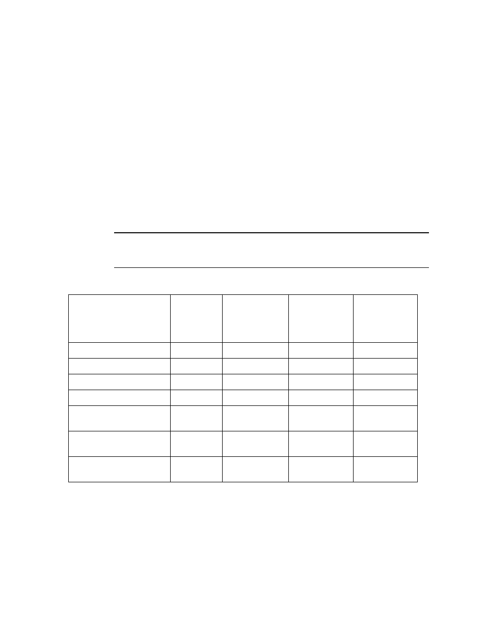
Table 4: Wire Size Guidelines for RKI Detector Head Wiring
Detector Head Type
Number of
Wires to
Controller
Max Distance
to Controller
w/18 Gauge
Wire
Max Distance
to Controller
w/16 Gauge
Wire
Max Distance
to Controller
w/14 Gauge
Wire
Direct Connect LEL
4
500 ft.
1,000 ft.
2,000 ft.
Direct Connect Oxygen
2
500 ft.
1,000 ft.
2,000 ft.
Direct Connect H2S
2
500 ft.
1,000 ft.
2,000 ft.
Direct Connect CO
2
500 ft.
1,000 ft.
2,000 ft.
Direct Connect ESM-01
type
2
500 ft.
1,000 ft.
2,000 ft.
2-Wire 4 - 20 mA
Transmitter
2
2,500 ft.
5,000 ft.
8,000 ft.
3-Wire 4 - 20 mA
Transmitter
3
2,500 ft.
5,000 ft.
8,000 ft.