Relays – RKI Instruments Beacon 410 User Manual
Page 13
Beacon 410 Gas Monitor Operator’s Manual
Internal Description • 9
•
AC terminal strip
The 3-point AC terminal strip is located above the controller terminal strip (see
Figure 1 on page 5). The AC terminal strip facilitates wiring connections to the AC
power source.
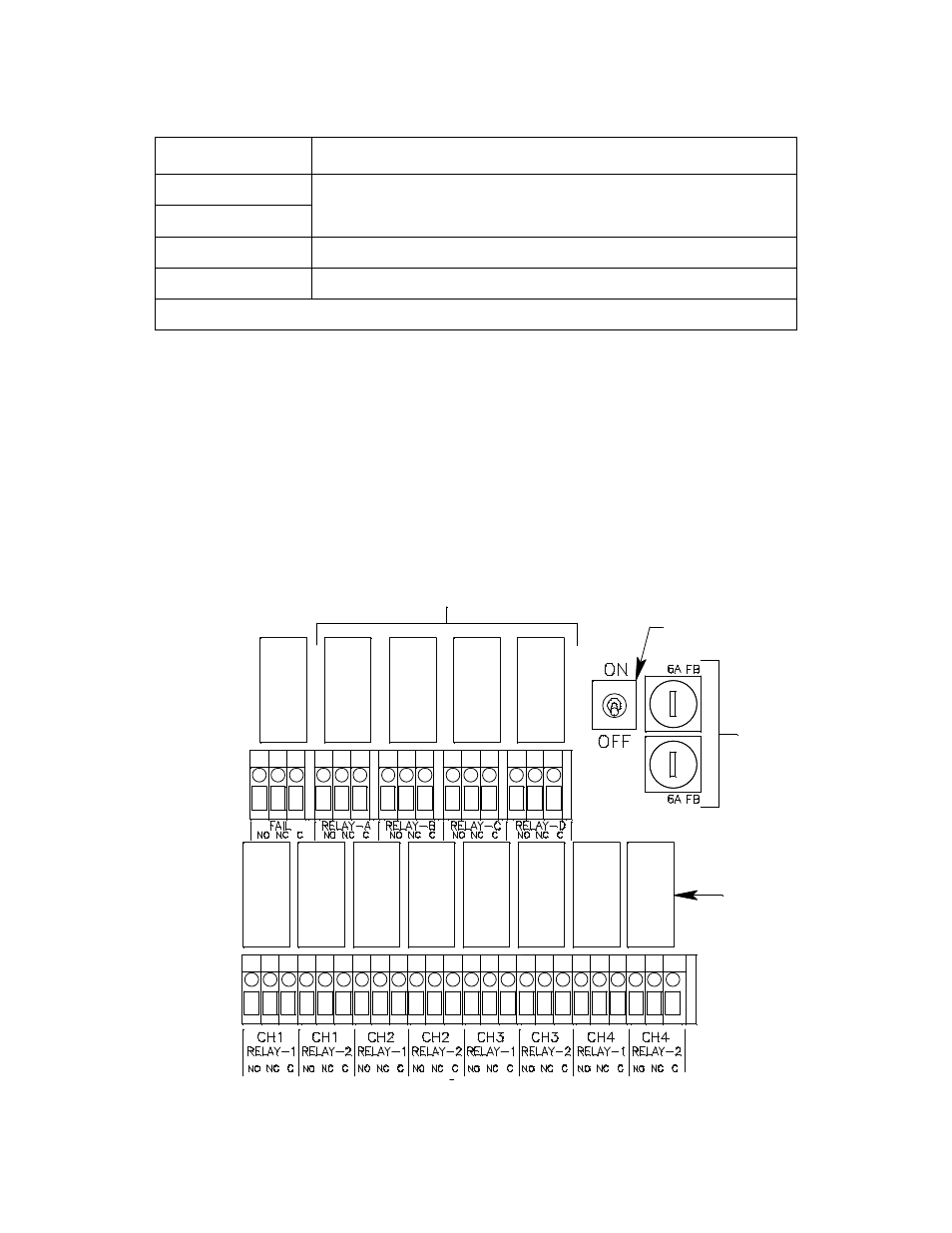
Relays
The Beacon 410 includes eight channel relays and one common fail relay. It also includes
four common/channel relays that can be defined as a group as channel or common relays.
All the relays have single-pole double-throw (SPDT) contacts, also known as form C
contacts, and are rated for 10 amps at 115 VAC (resistive). The contacts are available at
the channel alarm and common/channel alarm terminal strips and are labelled NO
(normally open), NC (normally closed), and C (common).
Figure 3: Beacon 410 Relay Allocation
Alarm Reset
Reset Switch Terminals (factory wired)
Alarm Reset
Alarm Buzzer +
Buzzer + connection (factory wired)
Alarm Buzzer -
Buzzer - connection (factory wired)
1
If 24 VDC is used as primary power source do not make wiring connections to the AC terminal strip.
Table 3: Terminal Assignments for the Controller Terminal Strip (Continued)
Terminal
Connects to:
Relay
D
CH 3
Relay
2
Relay
B
Relay
C
CH 1
Relay
1
CH 4
Relay
1
Power Switch
CH 2
Relay
2
Fail
Relay
CH 1
Relay
2
CH 4
Relay
2
CH 2
Relay
1
Relay
A
Common/Channel Relays
Channel
Relays
AC Fuses
CH 3
Relay
1