Connecting external alarms – RKI Instruments Beacon 410 User Manual
Page 23
Beacon 410 Gas Monitor Operator’s Manual
Wiring the Beacon 410 Gas Monitor • 19
Connecting External Alarms
Before connecting any external alarm devices to the relay contacts, make sure you know
how you want the devices to operate. For example, confirm under what alarm condition
you want a device to turn on or turn off and what channel is going to control the device.
Also make sure that the parameter settings that apply to the relays in the Global Menu and
the Configuration Menu are set so that the desired alarm device operation is obtained.
See “Viewing and Changing Global Parameters” on page 32 and “Viewing and Changing
Channel Parameters” on page 35 for information about the relay parameters.
Perform the following procedure to connect external alarm devices to the Beacon 410.
1.
Turn off or unplug all incoming power to the Beacon 410.
2.
Open the housing door, then place the power switch in the OFF position.
CAUTION: The power switch does not control DC input power.
3.
Locate the applicable alarm terminal strip (see Figure 1 on page 5).
4.
Install an appropriately rated cable bushing or conduit in an unused conduit hub on
the bottom of the Beacon 410.
5.
Guide the wiring of the external alarm device through the selected conduit hub on the
bottom of the Beacon 410 housing.
CAUTION: Do not route the external alarm wiring and detector head wiring through the
same conduit hub. The external alarm wiring may disrupt the transmission of
the detector head signal to the Beacon 410.
6.
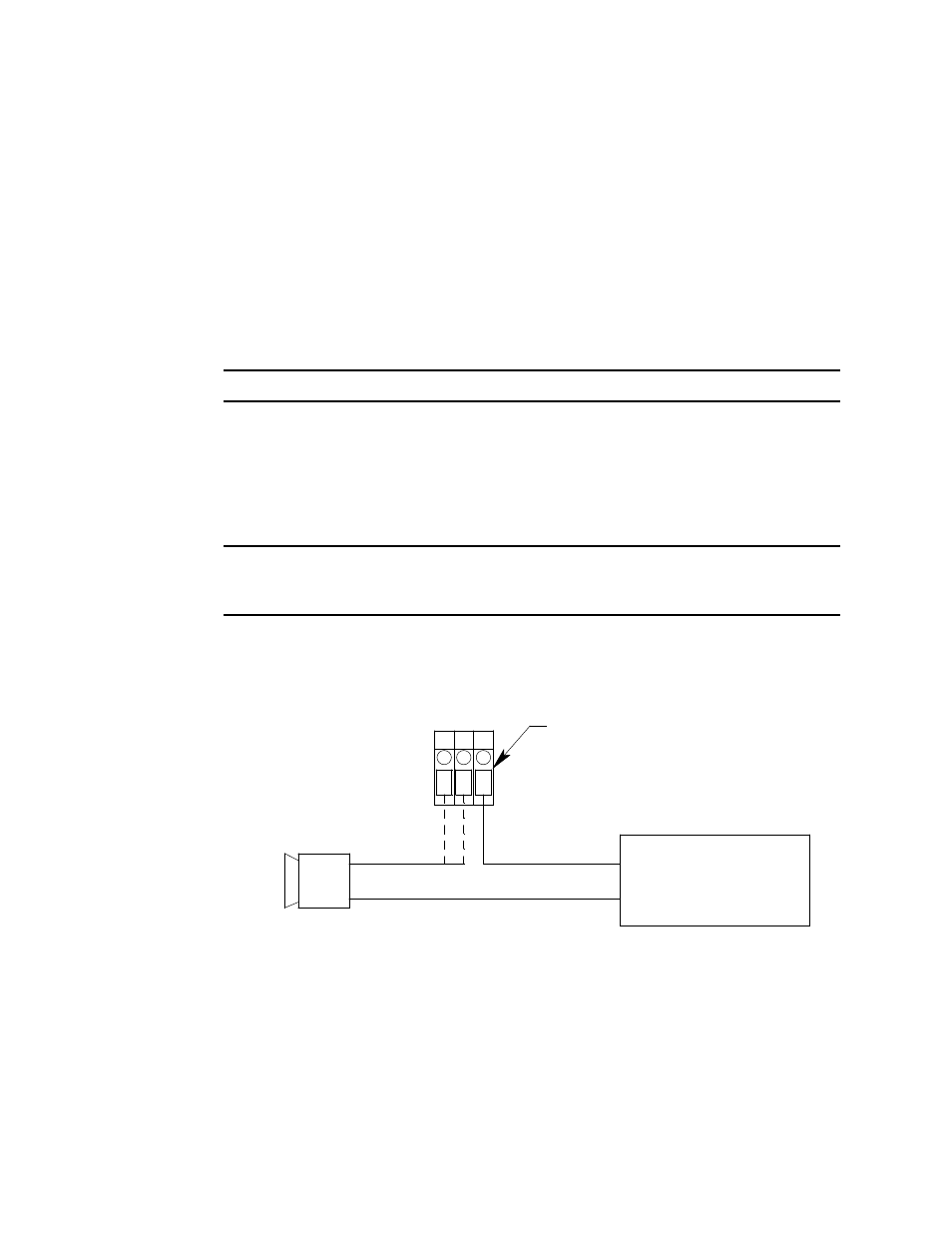
Connect the leads from the external alarm device and an external power source to the
selected channel alarm or common/channel alarm relay contact terminals as shown in
Figure 8.
Figure 11: External Alarm Wiring
7.
Repeat step 5 and step 6 for additional external alarm devices.
(+) H
(-) N
External
Power Source
Channel 1, Relay 1 Alarm Terminals
From Channel Alarm Terminal Strip
External Alarm Device
CH 1 RELAY 1
NO NC C