RKI Instruments Beacon 410 User Manual
Page 10
6 • Internal Description
Beacon 410 Gas Monitor Operator’s Manual
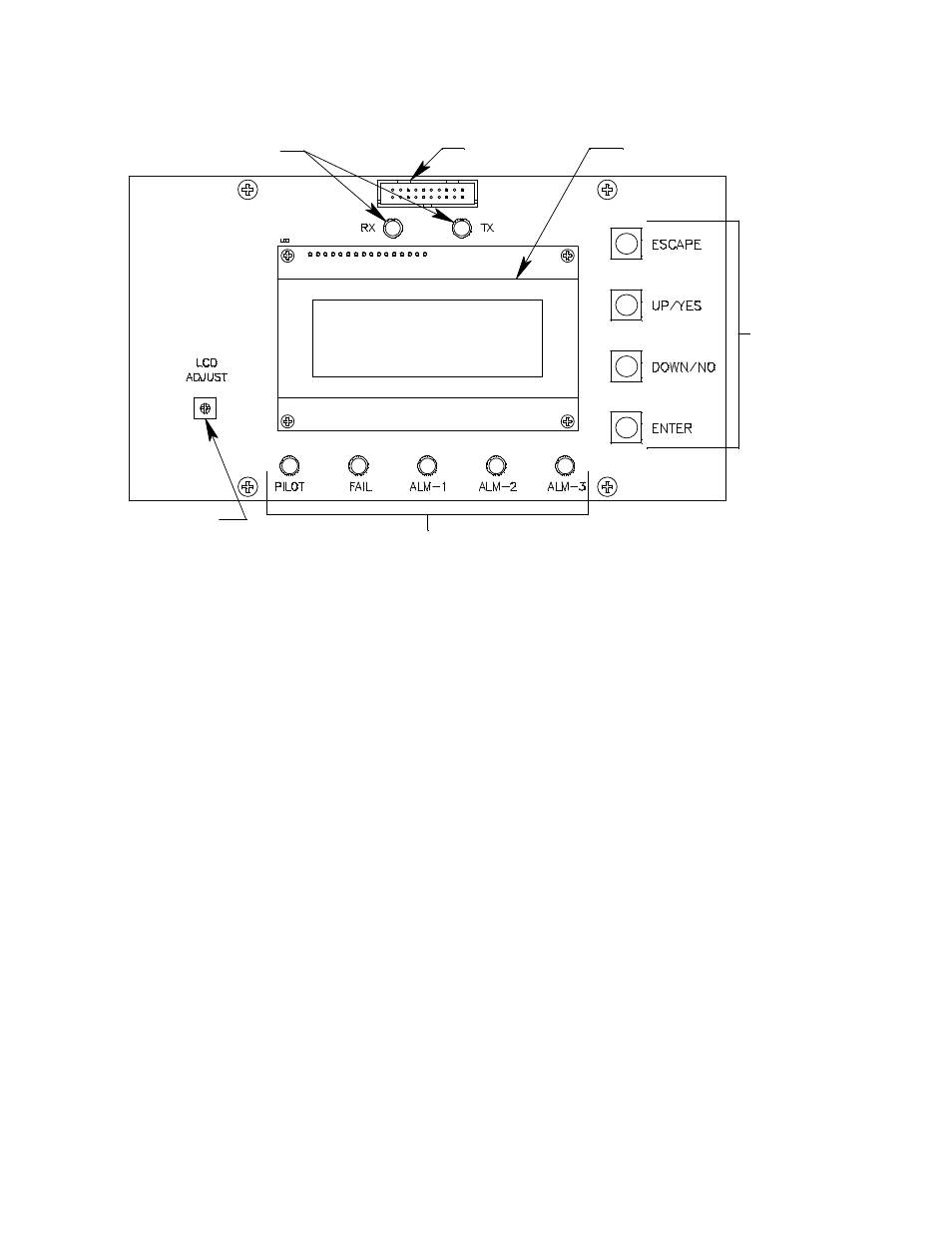
Figure 2: Control PCB Component Location
LCD Display
During normal operation, the four line display simultaneously indicates the target gas,
current gas reading, and measuring unit of each active channel. The display also shows
messages, settings, and other data when you are operating the various selection menus
and operating modes.
LCD Contrast Adjust Pot
The LCD contrast adjust pot is located to the left of the LCD. If the LCD contrast is too
dark or too light to read easily, use a small phillips screwdriver adjust it until you can easily
read the LCD.
Status LEDs
The Beacon 410 includes seven status LEDs that indicate the current status of the
monitor: the RX & TX LEDs, the pilot LED, the fail LED, the alarm 1 LED, the alarm 2 LED,
and the alarm 3 LED (see Figure 2).
•
RX & TX LEDs
These LEDs indicate data being received (RX) and transmitted (TX) when the Beacon
410’s Modbus output is operating.
•
Pilot LED
The PILOT LED is on when the Beacon 410 is receiving incoming power, either AC or
DC power.
•
Fail LED
The fail LED turns on when the Beacon 410 is experiencing a fail condition. A fail
condition can be caused by a failure within the Beacon 410 or the detector heads
Status LEDs
LCD Contrast
Adjust Pot
LCD Display
Display Cable
Connector
Status LEDs
Control
Switches