RKI Instruments Beacon 410 User Manual
Page 12
8 • Internal Description
Beacon 410 Gas Monitor Operator’s Manual
CAUTION: The strobe terminals are intended for use with the RKI supplied optional
strobe. Consult RKI Instruments, Inc. before attempting to use these
terminals for some other alarm device.
•
Detector/Transmitter Terminal Strips
Four detector/transmitter terminal strips are located along the bottom left side of the
main PCB (see Figure 1 on page 5). These four 11-point terminal strips facilitate
wiring connections to the detector heads. They also provide terminals to connect a
recording device to a 4 to 20 mA output for each channel. The top terminal strip is for
channel 1 connections and each subsequent strip is used for the next channel with the
bottom terminal strip being for channel 4 connections.
•
Channel Alarm Terminal Strip
A channel alarm terminal strip is located to the right of the channel 4
detector/transmitter terminal strip (see Figure 1 on page 5). This 24-point terminal
strip facilitates wiring external alarm devices (horn, light, etc.) to relay contacts that
are field configurable for alarm levels and operation and are controlled by individual
channels.The contacts are labelled NO (normally open), NC (normally closed),
and C (common). See “Viewing and Changing Global Parameters” on page 32 and
“Viewing and Changing Channel Parameters” on page 35 for instructions to configure
the operation of these contacts.
•
Common/Channel Alarm Terminal Strip
The common/channel alarm terminal strip is located in approximately the middle of the
main PCB above the channel alarm terminal strip. This 15-point terminal strip
facilitates wiring external alarm devices (horn, strobe, etc.) to relay contacts that are
field configurable as individual alarm contacts that are controlled by individual
channels or as common alarm contacts which are controlled by all channels. The
contacts are labelled NO (normally open), NC (normally closed), and C (common).
See “Viewing and Changing Global Parameters” on page 32 and “Viewing and
Changing Channel Parameters” on page 35 for instructions to configure the operation
of these contacts.
•
Controller terminal strip
The 9-point controller terminal strip is along the lower right side of the main PCB (see
Figure 1 on page 5). The controller terminal strip facilitates various internal and
external wiring connections. Table 3 lists the function of each terminal.
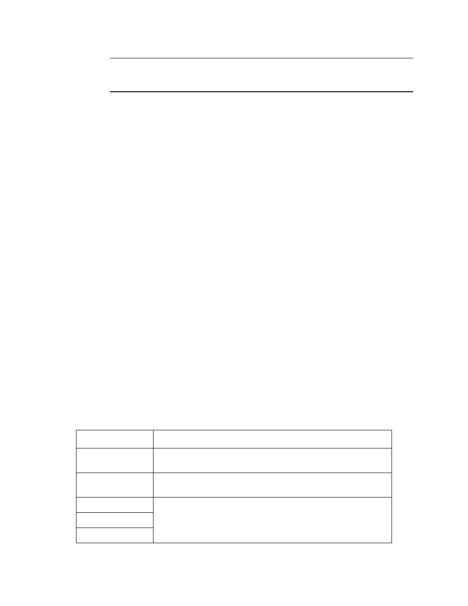
Table 3: Terminal Assignments for the Controller Terminal Strip
Terminal
Connects to:
EXT DC/24V BATT
+
+ connection from 24 VDC power source
1
(or 24 V backup battery)
1
EXT DC/24V BATT
-
- connection from 24 VDC power source
1
(or 24 V backup battery)
1
RS-485 A
RS-485 B
Allow connection of the Beacon 410 to a Modbus network
RS-485 C