Magna-loc, Ul 580 wind uplift information – Metal Sales Magna-Loc Installation User Manual
Page 26
© Metal Sales Manufacturing Corporation / Subject to change without notice 6/12
26
MAGNA-LOC
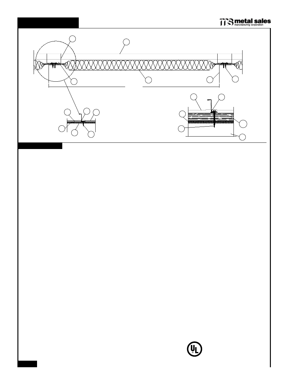
1. Metal Roof Deck Panels* No. 24 MSG min thick coated steel. Panel width, max 18 in., min 12 in.; rib height 2 in.
Panels continuous over two or more spans. The panel flat area may have optional striations or minor corrugations
placed at various locations in the panel flat area beginning min of 2 in. from side ribs. The upper flange of the panel
rib may be horizontal, or optionally formed down to form an angle of 0 degree to 90 degree between the vertical
segment and the top flange of the rib. End lap to occur adjacent to and within 12 in. of purlin (Item 6) with panels
overlapped 2 in. min. An end lap back-up-plate (Item 2A) to be used. A bead of sealant may be used at panel
end laps and side ribs. Ribs to be seamed with an electric or hand seaming tool to form a flange with a tight hem.
Seaming process to include the upper portion of the Panel Clips (Item 2).
METAL SALES MFG CORP - “Magna-Loc 18”, “Magna-Loc 16”
2. Roof Deck Fasteners* (Panel Clips) Located at side of panels over purlins (Item 6). (Max spacing 60 in. OC).
When wood thermal block (Item 4A) is used, clips to be located on top. Either of the following:
Fixed Clip (Not Shown) - One piece assembly fabricated from No. 22 MSG min thick steel, 3-1/2 in. wide.
Floating Clip - Two piece assembly with a base fabricated from No. 16 MSG min thick steel, 2 in. wide and a
top fabricated from No. 22 MSG min thick steel, 4-5/16 in. wide.
2A. End Lap Back-Up-Plate (Not shown) - No. 16 MSG min thick coated steel channel, 3 in. wide with two 3/8 in. deep
legs. Max length 74 in. Located under the panel end lap (50 ksi min yield strength).
2B. Roof Deck Fasteners*(Cinch Plate) (Optional) - (Not Shown) - width 1-5/16 in., length 18 in. max. Fabricated from
No. 20 MSG min thick stainless steel. Located over end lap.
2C. End Lap Back-Up-Plate (Optional) - (Not shown) - No. 16 MSG min thick coated steel. Width 11, 13 or 19 in.,
length 7 in. Two 3/4 in. by 3/4 in. tabs and a 1 in. deep vertical leg located at up-slope edge of panel. Used with
Item 2A when Item
*2B is not used (50 ksi min yield strength).
3. Fasteners (Screws) For panel clip-to-purlin attachment to be 1/4"-14 by min 1 in. long self drilling, self-tapping
hex-washer-head plated steel screws.
Two fasteners used per clip. Fasteners used at end lap to be one of the
following: No. 1/4-14 by 1 in. long Type AB point, self-drilling, self-tapping hex-washer-head plated or stainless steel
screws or No. 12-14 by 1-1/4 in. long self-drilling self-tapping hex-washer-head plated steel screws. Spacing for 16
in. wide panels to be a 1, 3, 4, 4, 3 in. pattern; spacing for 18 in. wide panels to be a 1-1/2, 3-1/2, 4, 4, 3-1/2, 1-1/2
in. pattern. When optional cinch plate (Item 2B) is used, four fasteners to be required, inserted into factory punched
guide holes.
4. Thermal Spacer (Optional) - Polyisocyanurate - 3/8 in. min, 2-3/8 in. max thick, 4 in. min width, length sized to fit
between panel clips (Item 2).
5. Insulation (Optional) - Any compressible blanket insulation 8 in. max thick before compression, or 6 in. max thick
when located between Thermal Spacer (Item 4) or Thermal Block (Item 4A) and purlin (Item 6).
6. Purlins No. 16 MSG min thick steel ( 50 ksi min yield strength ). Max spacing 60 in. OC.
Refer to General Information, Roof Deck Constructions for items not evaluated.
*Bearing the UL Classification Mark
Construction No. 506
October 16, 2001
Uplift - Class 90
Fire Not Investigated
UL 580 WIND UPLIFT INFORMATION
MAGNA-LOC
1
3
2
4A
5
6
60" MAX
3
1
2
4
6
5
4
2
1
5
6
3
Underwriters Laboratories Inc.
®
LISTED