Lenze MCH Series User Manual
Page 56
52
13435744_EDBMH01_v13
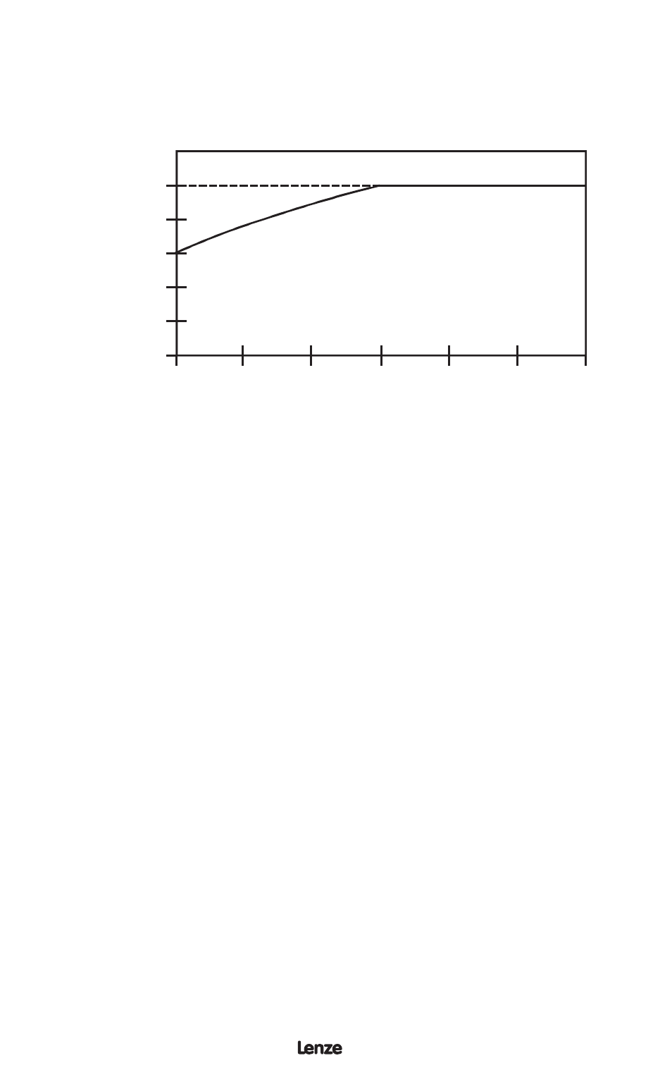
The MCH Series drive has two options for thermal overload protection. One depends
on the speed of the drive while the other does not. The diagram below illustrates the
difference between “speed compensated” and “non-compensated” thermal overload
protection.
FREQUENCY (Hz)
M
AXIMUM C
ONTINUOUS
OUTPUT CURRENT (%)
NON-COMPENSATED
SPEED C
OMPENSA
TED
10
20
30
40
50
60
20
40
60
80
100
The “speed-compensated” thermal overload circuit offers additional protection from high
load conditions at low speeds, where motor cooling is often less effective (e.g., motors
with shaft-mounted fans). As illustrated in the following diagram, the drive reduces the
allowable continuous output current when operating at frequencies less than 30 Hz.
Example 2:
A 480 Vac, 20 HP drive is operating a motor at 10 Hz. From the diagram,
a drive operating at 10 Hz can deliver about 75% of its output current
rating continuously. A 480 Vac, 20 HP drive’s output current rating is 27
Amps. Therefore, the drive would be able to operate continuously at 20
Amps. The drive would also be able to deliver 120% of that value (24
Amps) for one minute before tripping into an OVERLOAD fault.
The “speed compensated” thermal overload is the factory default and should be used
in applications where the motor does not normally experience high loads at low speeds
for extended periods of time.
NOTE 1: The above diagram is based on a MOTOR OVRLOAD setting of 100%. For
lower MOTOR OVRLOAD settings, reduce the % CURRENT values by the
same percentage. For example, if MOTOR OVRLOAD is set to 75%, reduce
the % CURRENT values by 25%. Therefore, the curve shifts down, but the
shape of the curve remains the same.
The “non-compensated” thermal overload circuit allows 100% current continuously, and
120% current for one minute, at all speeds. In the example above, the motor operating
at 10 Hz without “speed-compensated” protection would be allowed to operate
continuously at 27 Amps, and could draw 32.4 Amps for one minute before tripping.
Without sufficient motor cooling, this can result in motor failure due to overheating.
The “non-compensated” circuit is selected by setting Parameter 22 - TORQUE to CONST
/ NO COMP. The “non-compensated” setting should only be used in applications where
the motor is properly cooled at all speeds, or the motor manufacturer has approved the
motor for full-load operation at low speeds.
NOTE 2: The operation of the motor thermal overload circuit is affected by the setting
of Parameter 34 - LOAD MULTIPLY.