18 description of parameters, Input line voltage selection, Preset activation – Lenze MCH Series User Manual
Page 51
13435744_EDBMH01_v13
47
18
DESCRIPTION OF PARAMETERS
0
LINE VOLTS
This parameter calibrates the drive based on the input voltage, and can be set to AUTO,
HIGH, or LOW. When set to AUTO, the drive automatically selects HIGH or LOW based
on the incoming voltage.
This parameter can also be set “manually”, using the HIGH or LOW settings. Refer to
the Input Line Voltage table herein.
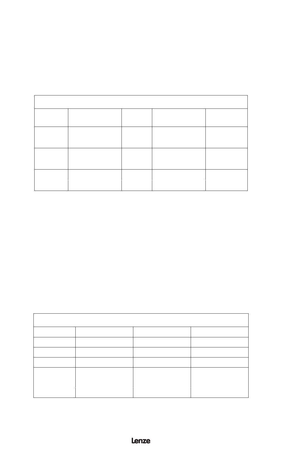
INPUT LINE VOLTAGE SELECTION
MODEL
RATED INPUT
VOLTAGE
INPUT
PHASE
ACTUAL INPUT
VOLTAGE
PARAM.
SETTING
MH200
240 / 200 Vac
3
220 - 240 Vac
HIGH
240 / 200 Vac
3
200 - 208 Vac
LOW
MH400
480 / 400 Vac
3
460 - 480 Vac
HIGH
480 / 400 Vac
3
380 - 415 Vac
LOW
MH500
590 / 480 Vac
3
575 - 600 Vac
HIGH
590 / 480 Vac
3
460 - 480 Vac
LOW
1-4
PRESET #1- #4
PRESETS are activated via contact closures between terminal TB-2 and terminals TB-
13A, TB-13B and TB-13C. These terminals must be programmed as preset selects
using Parameters 47 - 49: TB13A INPUT, TB13B INPUT, and TB13C INPUT.
In non-PID mode, PRESETS #1-#4 can be used as preset speeds. In this case, the
PRESETS are set in Hz, and can only be set to values within the range defined by the
minimum and maximum frequency (Parameters 10 and 11).
In PID mode, PRESETS #1, #2 and #4 can also be used as preset setpoints (PRESET
#3 cannot be used as a preset setpoint, only a preset speed). In this case, PRESETS
#1, #2 and #4 are set in actual PID units (the units selected in Parameter 31 - UNITS),
and can only be set to values within the range defined by the minimum and maximum
PID feedback (Parameters 75 and 76).
The Preset Activation table shows how each preset is selected using the TB-13
terminals. OPEN and CLOSED refer to the state of the TB-13 terminal relative to TB-2.
PRESET ACTIVATION
PRESET #
TB - 13A
TB - 13B
TB - 13C
1
CLOSED
OPEN
OPEN
2
OPEN
CLOSED
OPEN
3
OPEN
OPEN
CLOSED
CLOSED
CLOSED
OPEN
4
CLOSED
OPEN
CLOSED
OPEN
CLOSED
CLOSED