6 appendix, 1 technical data, 1 led indication – JUMO 707050 dTRANS T05 - Programmable 2-Wire Transmitter Operating Manual User Manual
Page 65: 2 analog input, Appendix, Technical data, Led indication, 1 led indication 6.1.2 analog input
27
6 Appendix
6.1
Technical data
6.1.1
LED indication
6.1.2
Analog input
All analog inputs are equipped with a digital filter of second order (filter constant adjustable from
0 to 10 s) and have a sampling rate of > 2 measurements per second.
RTD temperature probe
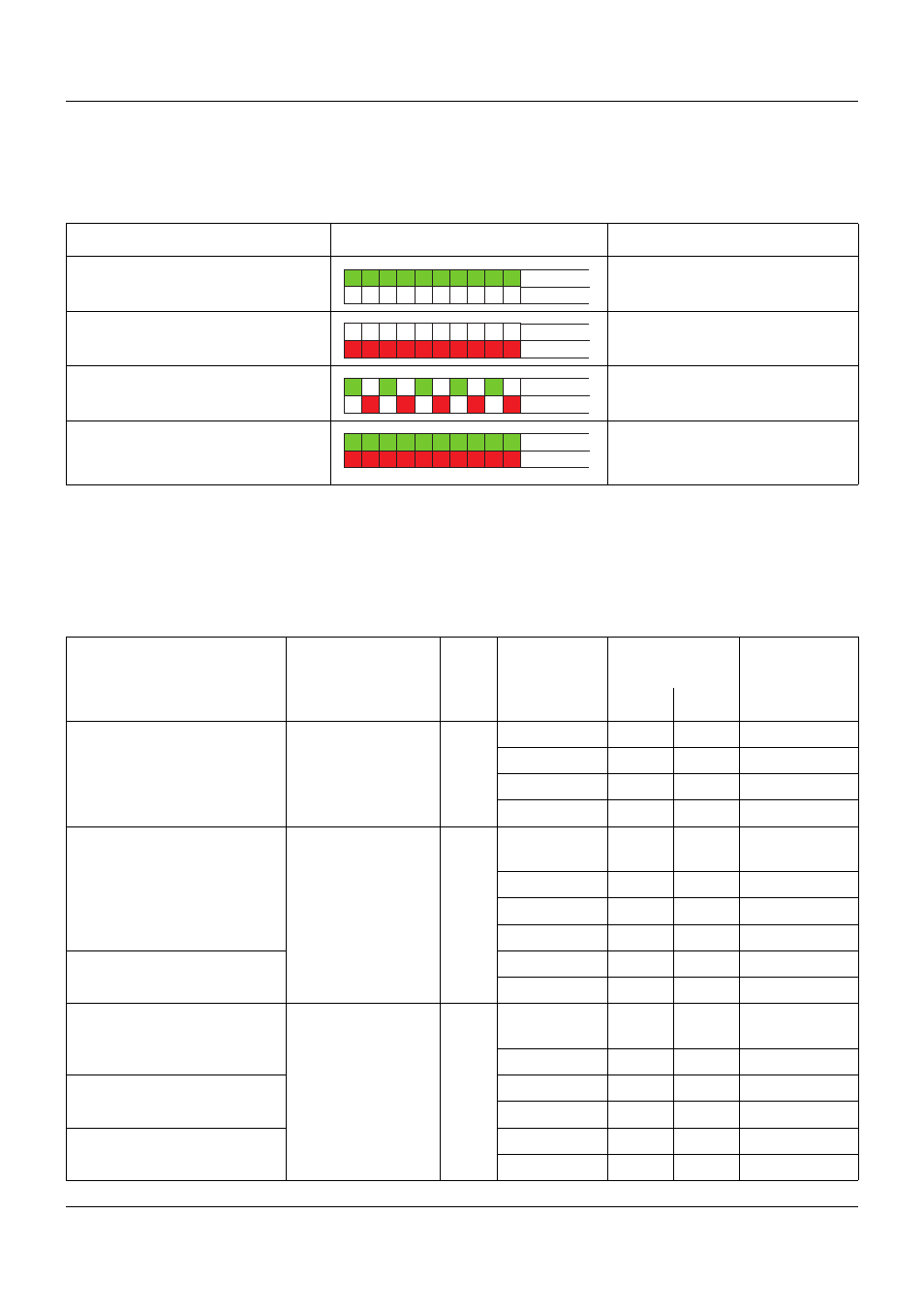
Display
Example
Meaning
The two-color LED is continually lit
green
OK
The two-color LED is continually lit
red
Sensor error
The two-color LED alternately
flashes red/green
Out of range
The two-color LED is continually lit
red and green simultaneously
Initialization phase,
Test mode
"Permanent Current Output" mode
Status green
Status red
Status green
Status red
Status green
Status red
Status green
Status red
Designation
Standard
ITS
Connection
type
Measuring
range in °C
Measuring
accuracy
a
Min.
Max.
Pt100
IEC 60751:2008
ITS-90 2/3-wire
-100
200
±0.2 K
Pt500
2/3-wire
-200
850
±0.4 K
Pt1000
4-wire
-100
200
±0.1 K
T
K
= 3.85 × 10
-3
1/K
4-wire
-200
850
±0.2 K
Pt100
GOST 6651-
2009 A.2
ITS-90 2/3-wire
-100
200
±0.2 K
T
K
= 3.917 × 10
-3
1/K
2/3-wire
-200
850
±0.4 K
4-wire
-100
200
±0.15 K
4-wire
-200
850
±0.25 K
Pt50
2/3-wire
-200
850
±0.5 K
T
K
= 3.91 × 10
-3
1/K
4-wire
-200
850
±0.3 K
Ni100
DIN 43760
IPTS-
68
2/3-wire
-60
250
±0.4 K
T
K
= 6.18 × 10
-3
1/K
4-wire
-60
250
±0.2 K
Ni500
2/3-wire
-60
250
±0.4 K
T
K
= 6.18 × 10
-3
1/K
4-wire
-60
250
±0.2 K
Ni1000
2/3-wire
-60
250
±0.4 K
T
K
= 6.18 × 10
-3
1/K
4-wire
-60
250
±0.2 K