Heidolph LABOROTA 20 automatic User Manual
Page 80
80
E
9.
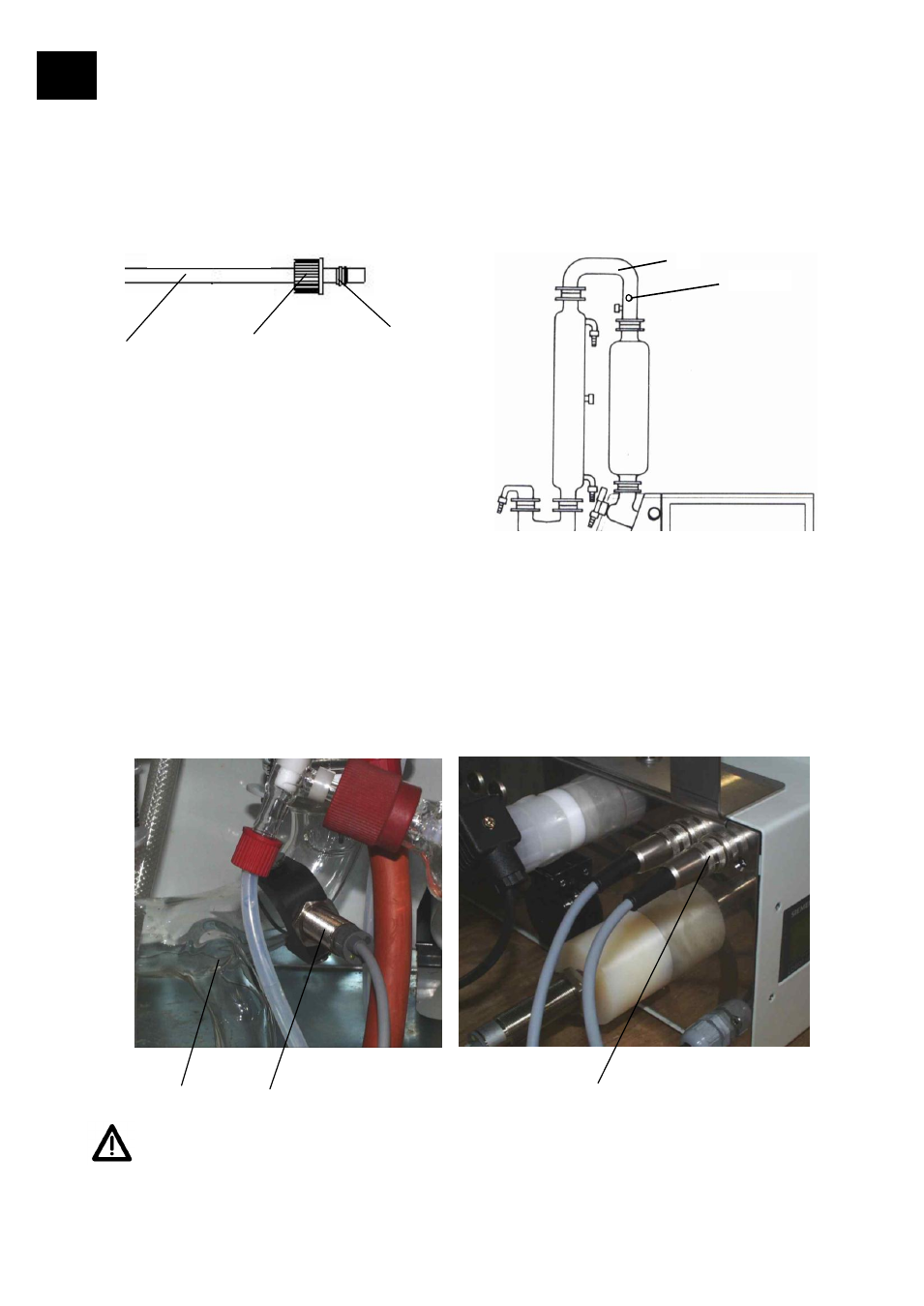
Connection of PTFE tubing (G)
9.1 Inlet tube
For the connection of the inlet tube (G) with inlet pipe (2) slide on screw cap (L) and locking ring
(M) on the feeding tube (G). Screw cap (L) on inlet tube (2).
9.2 Venting tube: condensate cooler
– glass set
For connection of venting tube with elbow of the glass set slide on screw cap (L) and locking ring
(M) on venting tube (G). Screw cap (L) on screw connector.
10. Electric connection of cut-out sensor
Cut-out sensor (11) is mounted to Y-connector (J) (also refer to page 84). After mounting of glass
ware according to figure on page 84, connect the plug (12) of cut-out sensor to the back-side of
automatic module and secure it with retaining ring by turning it to the right.
Attention: Make sure that the cylindrical body of the cut-out sensor (11) is
mounted in a horizontal position.
G
L
M
J
11
12
L;M;G
D