Plan conduit entry and wire routing, Drd semi-recessed installation kit – ETC Unison DRd Semi-Recessed Installation Kit User Manual
Page 5
E T C I n s t a l l a t i o n G u i d e
DRd Semi-Recessed Installation Kit
DRd Semi-Recessed Installation Kit Installation Guide
Page 5 of 8
Electronic Theatre Controls, Inc.
Plan Conduit Entry and Wire Routing
This section is specific to preparation of the DRd rack for installation into the recessed enclosure.
Openings are provided on the top and bottom of the recessed enclosure, providing conduit access to
the DRd enclosure.
Step 1:
Plan conduit and wire routing to the DRd rack enclosure. Reference the Unison DRd Rack
Enclosure Installation Manual “Wire Routing and Specification” section to plan wire
routing.
Step 2:
Mark the desired conduit access (top, bottom) on the DRd rack. Be sure to read and
comply with the label inside the DRd rack which details the recommended access
locations for conduit entry into the bottom of the rack.
Step 3:
Remove the power supply/dimming engine access panel to allow for better access in the
top of the DRd rack enclosure while roughing-in conduit and cable.
Step 4:
Punch holes into the planned conduit entry location of the DRd rack and install conduit
fittings or insert lining materials in the conduit opening.
Step 5:
Be sure there are minimal air gaps. Reference the Unison DRd Rack Enclosure
Installation Manual, “Sealing Rack Air Leaks” for instruction.
N o t e :
It may be helpful to temporarily install the DRd rack into the recessed enclosure and
mark the opening. This allows for certain placement of conduit entry.
Components on the bottom of the DRd rack prohibit conduit entry in certain locations.
A label denoting acceptable conduit access on the bottom panel of the DRd rack
defines the acceptable conduit access.
C A U T I O N :
Wire openings must have fittings, bushings, grommets or fiche paper lining material to
protect the wire and cable insulation from damage by sharp metal edges, and to
prevent air leaks.
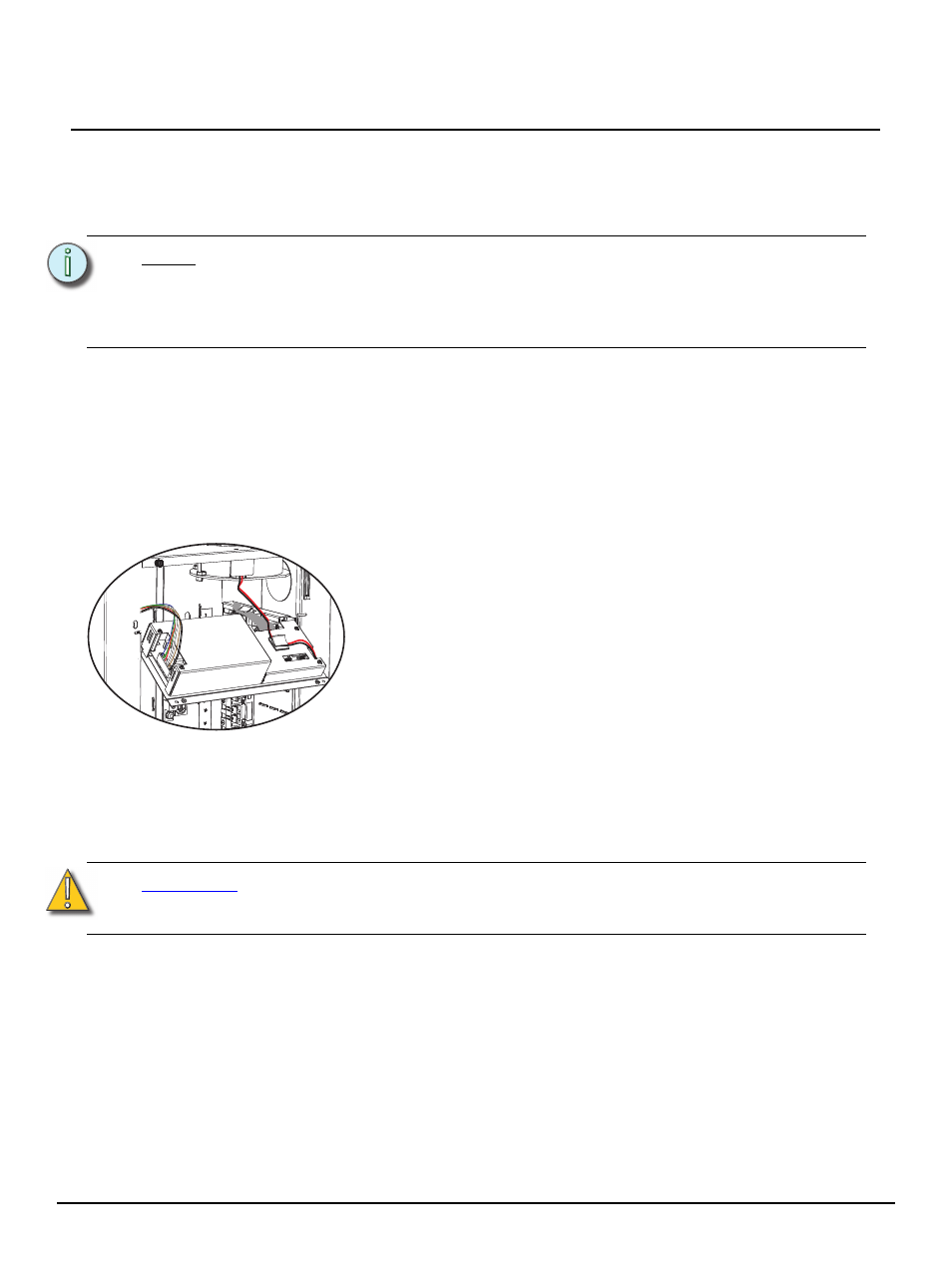
a: Loosen the two captured screws that secure the access panel.
b: Gently pull the panel straight down until the top of the access panel is
clear of the rack.
c: Tilt the supply access panel away from the rack.
d: Disconnect the three cables that are attached to the unit.
• For the cable bundle on the left side, squeeze the tabs on either
side of the connector and gently pull the cable until it is free.
• For the ribbon cable connected on the right rear side, release the
tabs on either side of the connector by sliding them opposite the
connector then gently pull the cable free.
• For the two wire cable on the right side, gently pull the connector
straight out.