I/o cables, Digital input (port j5) – ElmoMC AC Input Digital Servo Drives-Bassoon User Manual
Page 41
Bassoon Installation Guide
Installation
MAN-BASIG (Ver. 1.502)
41
3.5.7.
I/O Cables
The following table lists the I/O cables that you should connect according to your specific
requirements:
I/O Description
Total
Port
Digital input
6
J5
Digital output
2
J6
Analog input
1
J7
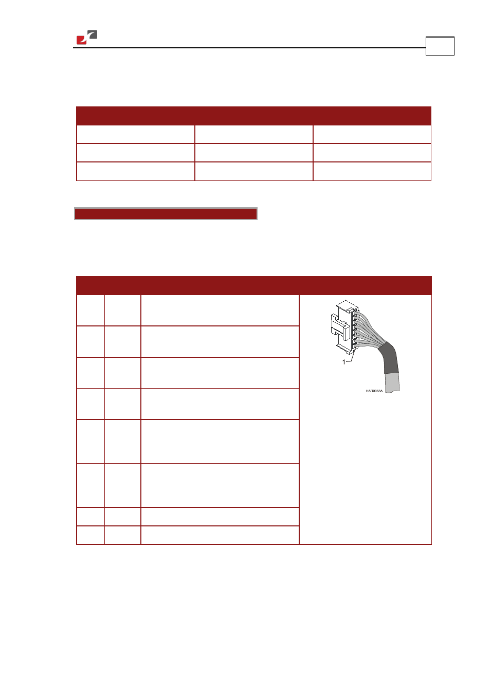
3.5.7.1.
Digital Input (Port J5)
Notes for connecting the digital input cable:
•
Use 24 or 26 AWG twisted pair shielded cable.
•
Connect the cable shield to the ground near the signal source (controller) according to the
manufacturer’s recommendations.
Pin Signal Function
Pin Positions
1
IN1
Programmable input 1
(general purpose, RLS, FLS, INH)
2
IN2
Programmable input 2
(general purpose, RLS, FLS, INH)
3
IN3
Programmable input 3
(general purpose, RLS, FLS, INH)
4
IN4
Programmable input 4
(general purpose, RLS, FLS, INH)
5
IN5
Programmable input 5
(event capture, Main Home,
general purpose, RLS, FLS, INH)
6
IN6
Programmable input 6
(event capture, Auxiliary Home,
general purpose, RLS, FLS, INH)
7
INRET
Programmable input return
8
INRET
Programmable input return
Table 12: Digital Input Cable Pin Assignments
- Gold Line Digital Servo Drives-Gold Bell (84 pages)
- Gold Line Digital Servo Drives-Gold DC Bell (61 pages)
- Gold Line Digital Servo Drives-Gold Whistle (85 pages)
- Gold Line Digital Servo Drives-Gold Solo Whistle (61 pages)
- Gold Line Digital Servo Drives-Gold Drum Ver 1_400 D-Sub connectors (67 pages)
- Gold Line Digital Servo Drives-Gold Drum Ver 1_400 RJ-45 connectors (67 pages)
- Gold Line Digital Servo Drives-Gold DC Whistle (61 pages)
- Gold Line Digital Servo Drives-Gold Drum HV (102 pages)
- Gold Line Digital Servo Drives-Gold Duo (59 pages)
- Gold Line Digital Servo Drives-Gold Solo Whistle Cable Kit (16 pages)
- Gold Line Digital Servo Drives-Gold Drum Cable Kit RJ-45 connectors (17 pages)
- Gold Line Digital Servo Drives-Gold DC Whistle Cable Kit (13 pages)
- Gold Line Digital Servo Drives-Gold Drum HV Cable Kit (18 pages)
- Gold Line Digital Servo Drives-Gold Duo Cable Kit (12 pages)
- Gold Line Digital Servo Drives-Gold Guitar (84 pages)
- Gold Line Digital Servo Drives-Gold Solo Guitar (65 pages)
- Gold Line Digital Servo Drives-Gold Cello (59 pages)
- Gold Line Digital Servo Drives-Gold Trombone (92 pages)
- Gold Line Digital Servo Drives-Gold Solo Trombone (110 pages)
- Gold Line Digital Servo Drives-Gold DC Trombone (69 pages)
- Gold Line Digital Servo Drives-Gold Tuba (81 pages)
- Gold Line Digital Servo Drives-Gold Bassoon (66 pages)
- Gold Line Digital Servo Drives-Gold Solo Guitar Cable Kit (12 pages)
- Gold Line Digital Servo Drives-Gold Cello Cable Kit (15 pages)
- Gold Line Digital Servo Drives-Gold Solo Trombone Cable Kit (16 pages)
- Gold Line Digital Servo Drives-Gold DC Trombone Cable Kit (15 pages)
- Gold Line Digital Servo Drives-Gold Tuba Cable Kit (20 pages)
- Gold Line Digital Servo Drives-Gold Bassoon Cable Kit (16 pages)
- ExtrIQ Gold Line Servo Drives-Gold Hornet (88 pages)
- ExtrIQ Gold Line Servo Drives-Gold Solo Hornet (90 pages)
- ExtrIQ Gold Line Servo Drives-Gold Eagle (68 pages)
- ExtrIQ Gold Line Servo Drives-Gold Hawk (90 pages)
- ExtrIQ Gold Line Servo Drives-Gold Panther (64 pages)
- ExtrIQ Gold Line Servo Drives-Gold Tiger (64 pages)
- Multi-Axis Motion Controller-Gold Maestro (32 pages)
- SimplIQ Digital Servo Drives-Bell Installation Guide (57 pages)
- SimplIQ Digital Servo Drives-Bell Getting Started (94 pages)
- SimplIQ Digital Servo Drives-Bell Command Reference (315 pages)
- SimplIQ Digital Servo Drives-Bell Evaluation Board User Guide (93 pages)
- SimplIQ Digital Servo Drives-Tweeter Installation Guide (71 pages)
- SimplIQ Digital Servo Drives-Whistle DC Installation Guide (75 pages)
- SimplIQ Digital Servo Drives-Whi-Solo Installation Guide (69 pages)
- SimplIQ Digital Servo Drives-Whi-Solo Cable Kit (10 pages)
- SimplIQ Digital Servo Drives-Whi-Duo Installation Guide (69 pages)
- SimplIQ Digital Servo Drives-Whi-Trio Installation Guide (62 pages)