4 re-aligning torque hub input coupling, Equipment required, Procedure – JLG 510AJ Service Manual User Manual
Page 84: 5 drive motor, Description, Shaft seal replacement, Re-aligning torque hub input coupling -42, Equipment required -42 procedure -42, Drive motor -42, Description -42 shaft seal replacement -42
SECTION 3 - CHASSIS AND TURNTABLE
3-42
– JLG Lift –
3121181
3.4
RE-ALIGNING TORQUE HUB INPUT COUPLING
The following procedure applies to torque hubs with integral
brakes.
Equipment Required
1.
Hydraulic power supply (hand pump) capable of pro-
ducing 200 psi (13.8 bar).
2.
Hydraulic fittings to adapt hydraulic supply to brake
release port on hub.
Procedure
1.
Using appropriate fittings, connect a line from hydraulic
power supply to brake port.
2.
Pressurize brake release port 155 to 200 psi (10.6 to 13.8
bar) to release brake.
3.
Verify that the brake is released by rotating the input
coupling or hub spindle.
4.
Once the brake is released, the input coupling will be
free to re-align with the drive motor.
5.
Install drive motor on hub, then release hydraulic pres-
sure at brake release port. Coupling will remain in posi-
tion.
6.
Disconnect the hydraulic power supply and reconnect
the line going into the brake release port.
3.5
DRIVE MOTOR
Description
Drive motors are low to medium power, two-position axial pis-
ton motors incorporating an integral servo piston. They are
designed for operation in both open and closed circuit appli-
cations. The standard control is a direct acting single line
hydraulic control. The integral servo piston controls motor dis-
placement.
Motors are spring biased to maximum displacement and
hydraulically shifted to minimum displacement. Minimum and
maximum displacement can be set with fixed internal stops.
The large diameter servo piston allows smooth acceleration
and deceleration with relatively large circuit orificing.
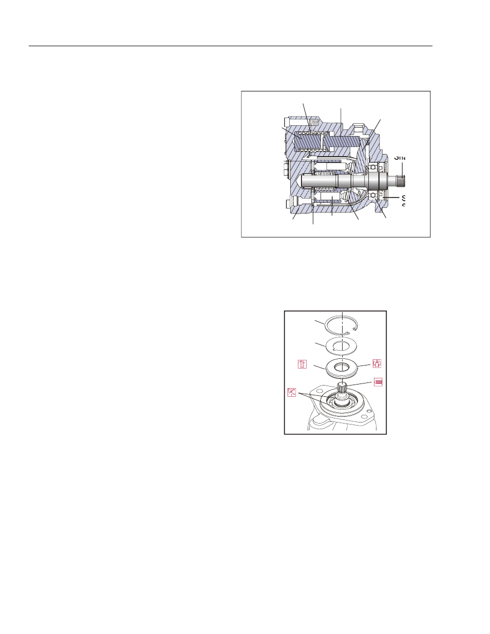
Shaft Seal Replacement
REMOVAL
1.
Remove snap ring (1) retaining shaft seal and support
washer.
2.
Remove the support washer (2).
3.
Carefully pry out shaft seal (3).
NOTE:
To avoid damaging shaft during removal, install a large
sheet metal screw in chuck of a slide hammer. Drive screw
into seal surface and use slide hammer to pull seal.
4.
Discard seal.
Bias spring
Servo piston
Swashplate
Output
Shaft
Piston
Slipper
Cylinder
Block
Endcap
Shaft
Seal
Bearing
Minimum
Angle
Stop
Valve plate
Figure 3-24. Drive Motor Cross Section
1
2
3
1.
Snap Ring
2.
Support Washer
3.
Shaft Seal
Figure 3-25. Removing Shaft Seal