Reach specifications, Chassis, 5 function speeds – JLG 510AJ Service Manual User Manual
Page 18: Machine orientation when doing speed tests, Test notes, Reach specifications -2 chassis -2, Function speeds -2, Reach specifications -2, Chassis specifications -2, Function speeds (in seconds) -2
SECTION 1 - SPECIFICATIONS
1-2
– JLG Lift –
3121181
Reach Specifications
Chassis
1.5
FUNCTION SPEEDS
Machine Orientation When Doing Speed Tests
Lift: Boom Retracted. Telescope Retracted. Lift Up, Record
Time, Lift Down, Record Time.
Swing: Boom at Full Elevation. Telescope Retracted. Swing the
Turntable to the end stop. Swing the Opposite Direction,
Record Time.
Telescope: Boom at Full Elevation; Telescope Retracted; Tele-
scope Out, Record Time. Telescope In, Record Time.
Drive: Test to be done on a smooth level surface. Drive Select
Switch should be set at 2WD High Engine. Start approximately
25 ft. (7.62 m) from starting point so that the unit is at maxi-
mum speed when starting the test. Results should be recorded
for a 200 ft. (60.96 m) course. Drive Forward, record time. Drive
Reverse, Record Time.
Drive (Above Horizontal): Test should be done on a smooth
level surface. Set Drive Select Switch to High Engine, High
Drive. The Platform Speed Knob should be selected out of the
creep speed. This verifies switches are working when boom is
above horizontal. Results should be recorded for a 50 ft.
course. Drive Forward, Record Time. Drive Reverse, Record
Time.
Platform Rotate: Platform level and completely rotated one
direction. Rotate the opposite direction, Record Time. Rotate
the other direction, Record Time.
Articulating Jib: Platform level and centered with the boom.
Start with the Jib down. Jib Up, Record Time. Jib Down, Record
Time.
Lower Lift: Upper Boom horizontal. Telescoped In. Lower Lift
Up, Record Time. Lower Lift Down, Record Time.
Test Notes
1.
Start Stop watch with function, not controller or switch.
2.
Drive test results reflect 12x16.5 tires.
3.
All speed tests are run from the platform. Speeds do not
reflect ground control operation.
4.
Platform speed knob control must be at full speed
(turned clockwise completely).
5.
Function speeds may vary due to cold, thick hydraulic
oil. Test should be run with oil temperature above 100° F
(38° C).
6.
Some flow control functions may not work with the
speed knob clicked into creep position.
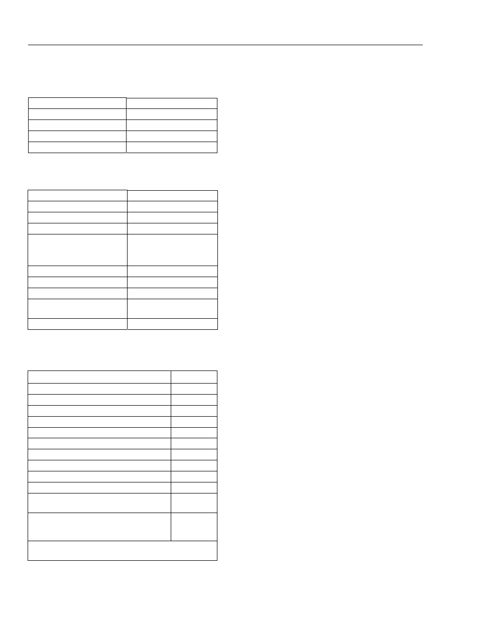
Table 1-7. Reach Specifications
Max. Platform Height
51.8 ft. (15.81 m)
Max. Horizontal Reach
31.1 ft. (9.48 m)
Up & Over Height
24.08 ft. (7.34 m)
Jib Length
4.5 ft. (1.37 m)
Jib Angle
135° (+70°, -65°)
Table 1-8. Chassis Specifications
Swing
357° non-continuous
Platform Capacity
500 lbs. (230 kg)
Rated Gradeability
40%
Max. Tire Load
7900 lb. (3583 kg)
Max. Ground Bearing Pressure
Std. Tire
Flotation Tire
48 psi (3.37 kg/cm
2)
36 psi (2.53 kg/cm
2)
Axle Oscillation
8 in. (0.2 m)
Drive Speed
4.5 mph (7.2 kph)
System Voltage
12 Volts
Max. Hydraulic System Operating
Pressure
4500 psi
(310 bar)
Gross Machine Weight
16,104 lbs. (7305 kg)
Table 1-9. Function Speeds (In Seconds)
Function
Speed
Main Lift Up
24-28
Main Lift Down
20-24
Swing Right & Left*
85-95
Telescope Out
18-22
Telescope In
12-16
Platform Rotate Right & Left**
25-32
Jib Up
21-31
Jib Down
19-25
Lower Lift Up
30-38
Lower Lift Down
22-28
Drive (4WD High Engine)
29-31
(4.5 MPH)
Drive above Horizontal
(50 ft.)
46-68
(0.75 - 0.50
MPH)
*Max 10% Difference Between Left & Right
**Max 15% Difference Between Left & Right