Axle lockout cylinder (inside frame), Axle lockout cylinder (inside frame) -34, Cylinder barrel support -34 – JLG 510AJ Service Manual User Manual
Page 254: Cylinder head removal -34, Cylinder rod support -34
SECTION 5 - HYDRAULICS AND HYDRAULIC SCHEMATICS
5-34
– JLG Lift –
3121181
Axle Lockout Cylinder (Inside Frame)
Refer to Figure 5-74.
DISASSEMBLY
CONTAMINATION MAY DAMAGE EQUIPMENT. DISASSEMBLE CYLINDER ON A
CLEAN WORK SURFACE IN A DIRT FREE WORK AREA.
1.
Connect a suitable auxiliary hydraulic power source to
cylinder port block fitting.
DO NOT FULLY EXTEND CYLINDER TO THE END OF STROKE. RETRACT CYLINDER
SLIGHTLY TO AVOID TRAPPING PRESSURE.
2.
Operate hydraulic power source and extend cylinder.
Shut down and disconnect power source. Support cylin-
der rod as needed.
3.
Remove cartridge valves (4) from valve block. Discard O-
rings.
4.
Remove bleeder valves (3) if damaged or leaking.
5.
Place cylinder barrel in a suitable holding fixture. Tap
around outside of cylinder head retainer with suitable
hammer to break thread-locking compound.
Figure 5-71. Cylinder Barrel Support
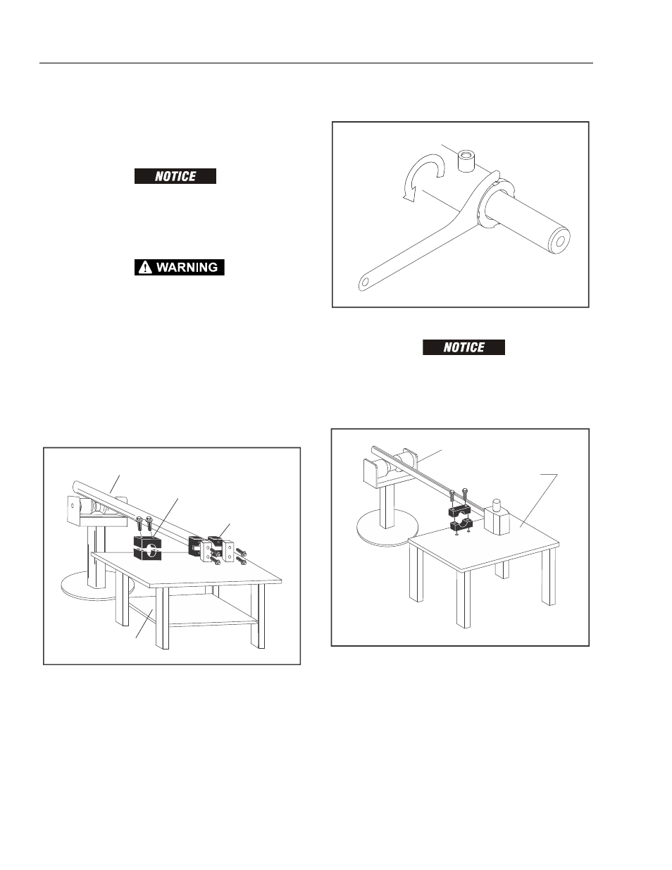
6.
Unscrew cylinder head with spanner.
Figure 5-72. Cylinder Head Removal
PULLING ROD OFF-CENTER CAN DAMAGE PISTON AND C YLINDER BARREL
SURFACES. USE EXTREME CARE WHEN REMOVING CYLINDER ROD, HEAD, AND
PISTON.
7.
Clamp barrel securely. Pull rod assembly from barrel.
Figure 5-73. Cylinder Rod Support
ROD SUPPORT
PROTECTED ROD CLAMP
BARREL CLAMP
SUPPORT TABLE
SUPPORT TABLE
ROD SUPPORT