Spindle-brake disassembly, Spindle-brake disassembly -8, Spindle brake disassembly -8 – JLG 510AJ Service Manual User Manual
Page 50
SECTION 3 - CHASSIS AND TURNTABLE
3-8
– JLG Lift –
3121181
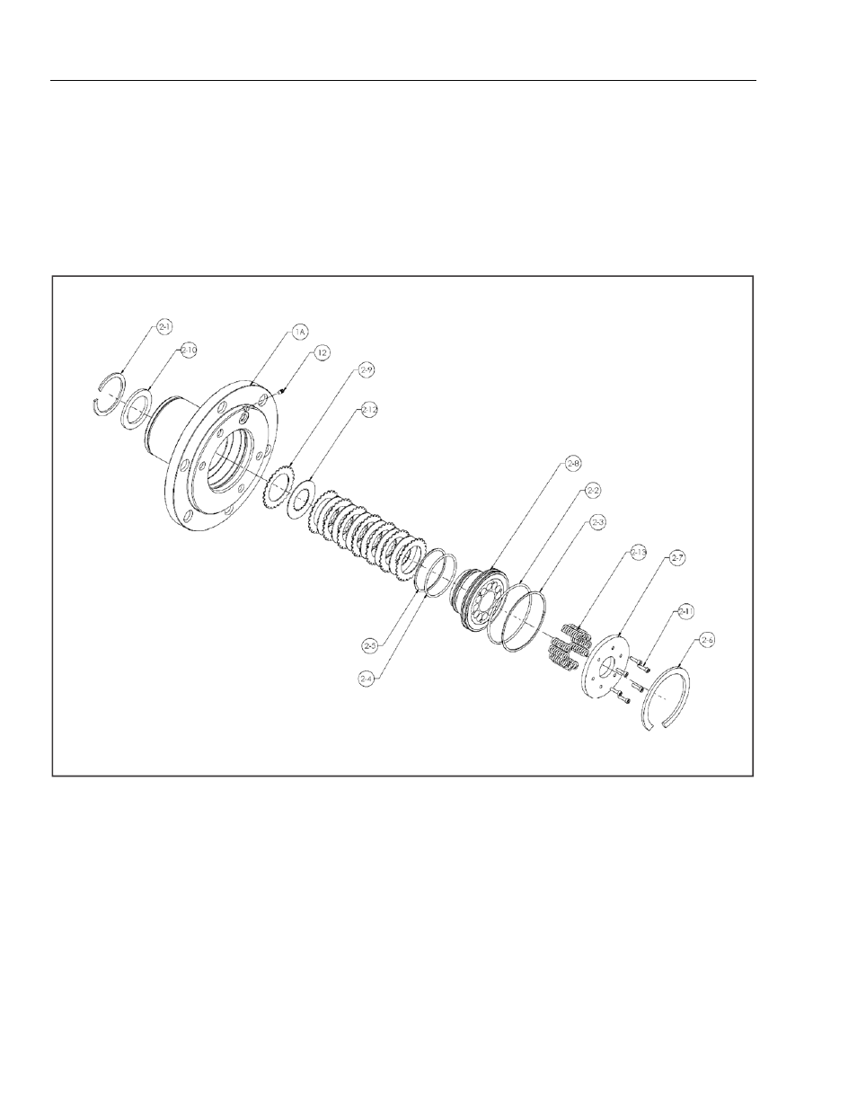
Spindle-Brake Disassembly
NOTE:
This procedure applies only to units with integral input
brake (2).
NOTE:
For this procedure, use the Brake Assembly Drawing, which
will show the proper balloon numbers for the individual
brake components. In the following instructions, if the
number has a “-” between two numbers, it refers to the
Brake Assembly Drawing only and NOT the Torque Hub
Assembly Drawing.
NOTE:
The Pressure Plug (12) requires a special tool for installa-
tion. It is not recommended to remove this plug unless it is
leaking. The plug is called a Koenig Expander. The installa-
tion tool is not supplied by Fairfield manufacturing, but
can be supplied by the manufacturer of the Koenig
Expander, Sherex Industries, or one of their distributors.
1-A. Spindle
2-2. O-ring
2-5. Back-up Ring
2-8. Piston
2-11. Capscrew
12. Pressure Plug
2-3. Back-up Ring
2-6. Internal Circlip
2-9. Stator
2-12. Rotor
2-1. Internal Circlip
2-4. O-ring
2-7. End Plate
2-10. Spacer
2-13. Compression Spring
Figure 3-6. Spindle Brake Disassembly