Installation instruc tio ns – Poison Spyder JK ROCKBRAWLER REAR BUMPER WITH TIRE CARRIER User Manual
Page 4
INSTALLATION INSTRUC
TIO
NS
©2014 POISON SPYDER CUSTOMS, INC. • 951-849-5911 • WWW.POISONSPYDER.COM
Poison Spyder Customs • JK ROCKBRAWLER REAR BUMPER
Page 4
15. Wearing a latex or nitrile glove, use your
fingers to apply a light sheen of grease to the
bare metal surfaces of the inside of the tire
carrier hinge housing and bearing races, as
well as the hinge spindle on the bumper (do
not coat the threads for the spindle nut). This
will help discourage rust formation on these
bare metal surfaces.
16. Insert a Tapered Roller Bearing into the
pre-installed Lower Race, inside the Hinge
Housing. Ensure that it seats correctly and
“feels right” in the race. Excess grease may
hold it in place temporarily, but it may be
helpful to turn the tire carrier upside down
until the next step is completed.
17. Use a bearing seal driver tool to carefully
install the grease seal into the bottom of the
hinge housing. If the proper tool is not available,
the step may be performed by carefully using
a large socket of the approximate diameter
of the seal and a soft dead-blow hammer to
work the seal into its seat. Be very careful
to drive the seal in evenly, do not let it get
misaligned while driving it in.
18. Install the Tire Carrier onto the bumper,
carefully guiding the hinge housing down
over the hinge spindle. Be careful not to
damage the grease seal when lowering the
tire carrier on to the spindle. There is a very
tight-tolerance slip-fit between inner diameter
of the tapered roller bearing and its seating
surface on the spindle. Be careful not to
let the bearing get misaligned as you lower
the carrier onto the bumper. Have a friend
support the opposite end of the tire carrier
during this and the next two steps.
FIGURE 8
19. Install the remaining Tapered Roller
Bearing by dropping it down over the hinge
spindle, narrow end pointed downward.
Carefully slide it down the spindle until it is
seated into the upper race.
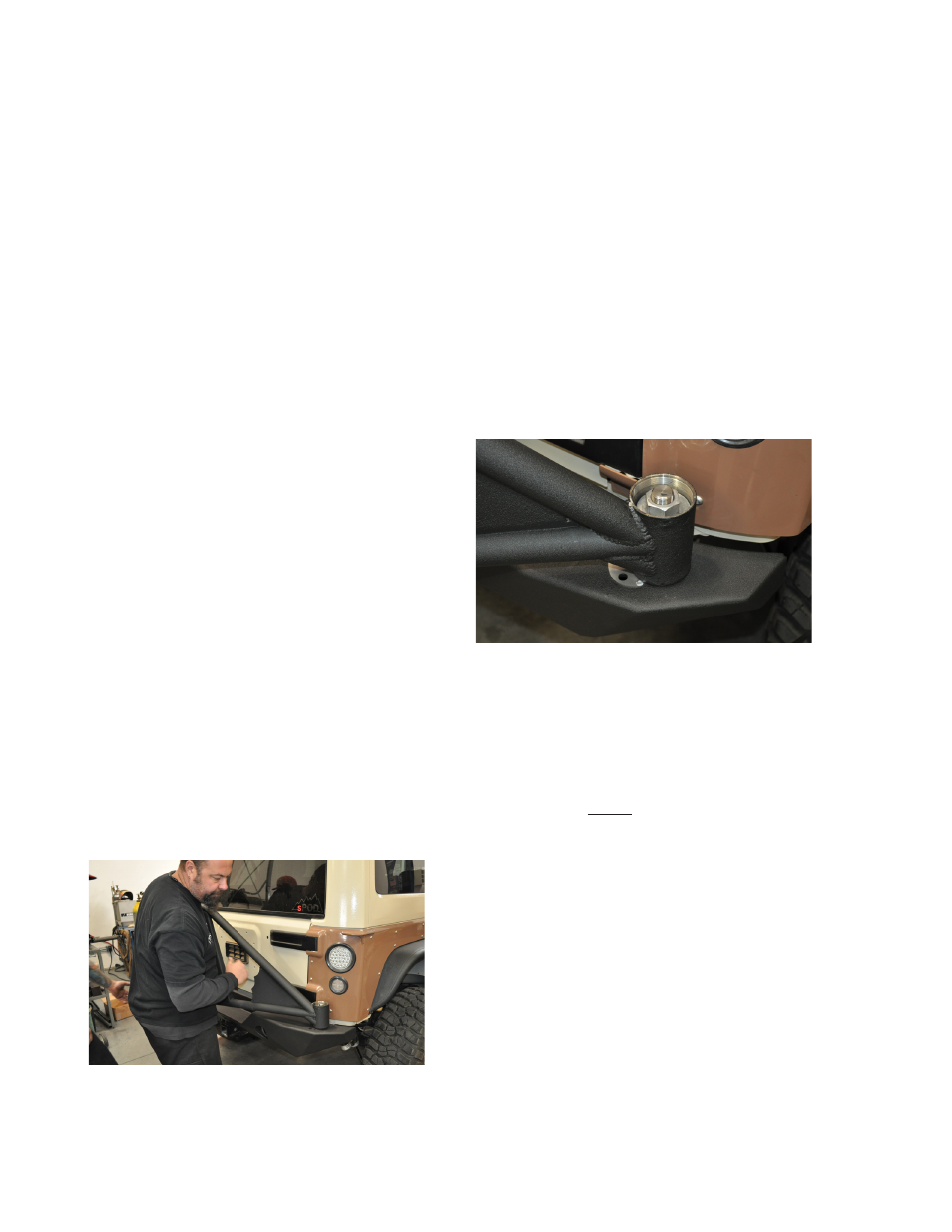
20. Apply some anti-sieze thread lubricant to
the threads on the spindle. Install the large 1”
Flat Washer next on the spindle, followed by
the 1”-14 Grade C All-Metal Lock Nut. Tighten
the lock nut until it just touches the washer and
bearing, then have your friend slowly swing
the tire carrier back and forth as you tighten
the lock nut the rest of the way. We can not
supply a torque specification for this nut, just
get it as tight as it takes to properly seat the
bearings and provide smooth operation of
the tire swing without any “play”. You may
need to re-tighten this nut several times until
it permanently seats.
FIGURE 9
21. Install the Hinge Cap O-Ring onto the
outside of the threads of the Billet Hinge
Cap, just under the head of the cap (NOTE:
this may have already been done prior to
shipment).
22. Thread the Hinge Cap onto the Hinge
Housing and lightly tighten with a 2-12”
wrench, socket with ratchet or big-ass
crescent wrench. Note that you may have to
remove it in later steps to further tighten the
spindle lock nut, so don’t fully tighten the cap
until installation is complete.
23. Install the Lock Pin Assembly into the
provided housing (on the side of the hinge
bearing housing). Use an open-end wrench
to carefully tighten the hex head of the pin
assembly.