Installation instruc tio ns – Poison Spyder JK ROCKBRAWLER REAR BUMPER WITH TIRE CARRIER User Manual
Page 3
INSTALLATION INSTRUC
TIO
NS
©2014 POISON SPYDER CUSTOMS, INC. • 951-849-5911 • WWW.POISONSPYDER.COM
Poison Spyder Customs • JK ROCKBRAWLER REAR BUMPER
Page 3
6. Remove the bumper from the Jeep.
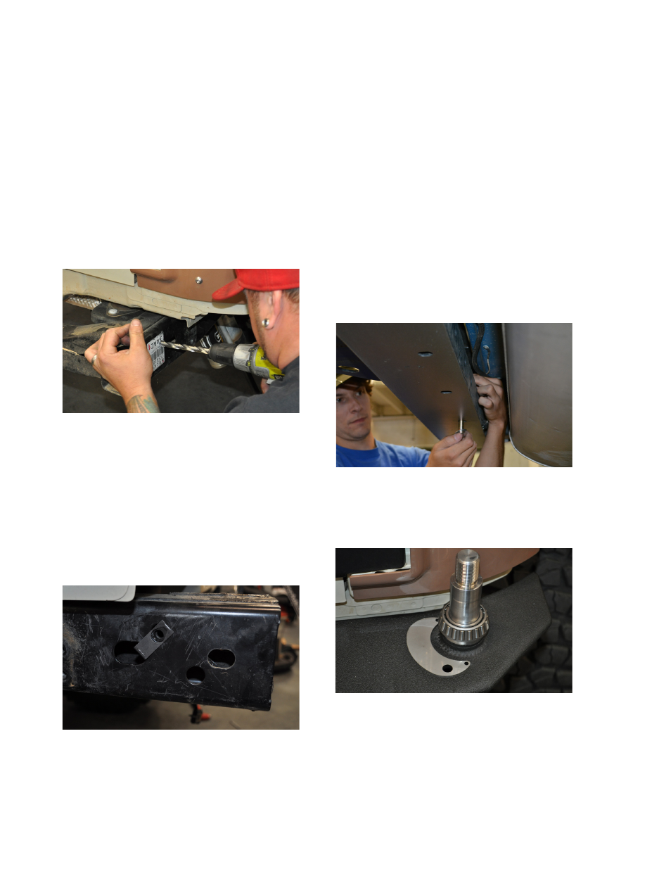
7. Drill upward through the crossmember,
at the hole location marked in the previous
step. Start with a smaller drill size such as
1/4”, then step up to the 1/2” bit for the final
hole size. Drill through both the bottom and
top surfaces of the bumper, trying to hold the
drill perpendicular so the holes are vertically
aligned.
8. Drill the third bolt hole on the sides of each
frame rail to 1/2”. It is best to start with a
smaller drill size such as 1/4”, then step up to
the 1/2” size bit.
FIGURE 3
9. Apply touch-up paint to the bare metal
around the edge of the holes that were drilled
in the previous steps. Properly coating these
areas at this time will help to prevent rust in
the future.
10. Insert a 3/8-16 Clip Nut through the oblong-
shaped hole in the frame rail, and clip it into
the new hole just drilled. Make sure the
extruded thread barrel of the clip nut points
inward. Do this on both frame rails.
FIGURE 4
11. Reinstall the RockBrawler™ bumper
using the OE hardware in the two original
bolt locations on the sides of the frame rail,
and a supplied 3/8-16 X 1 Gr8 Hex Head Cap
Screw with 3/8 Flat Washer in each of the
new bolt locations on the outside of the frame
rails. Note that both the bumper’s mount
flanges are inserted between the outside of
the frame rail and the sway bar bracket.
12. Insert the 1/2-13X4-1/4 Gr8 Hex Head Cap
Screws into the two outside holes along the
underside of the bumper, with a 1/2 Gr8 Flat
Washer under the bolt head. Insert the bolt
up through the holes in the bumper and both
top and bottom surfaces of the crossmember.
Secure them with a 1/2-13 Gr8 Nylon Insert
Lock Nut and 1/2 Gr8 Flat Washer, where they
protrude through the top of the crossmember.
You may have to do this by feel, as the nuts
and washers will be threaded on inside the
bumper shell,
FIGURE 5
13. Use the two (2) supplied 3/16” pop rivets
to attach the crescent-shaped stainless steel
Lock Pin Slider Plate to the bumper at the
base of the hinge spindle.
FIGURE 7
14. Wearing latex or nitrile gloves, “Pack” the
two tapered roller bearings with a quality
wheel bearing grease by hand or with a
bearing packing tool. The two matching
bearing races are already pressed in to the
tire carrier hinge housing.