Figure 3-4: tpm relief valve control, 4 cavitation, Figure 3-5: sample, cavitation regions – Hale MBP Booster User Manual
Page 37
❑ Operation
36
Silencer Series Booster Pump, p/n: 029-0020-83-0
The amber indicator light illuminates. (See
Figure 3-4: “TPM Relief Valve Control.”)
3. Turn the hand wheel slowly clockwise until the
indicator light goes out. The relief valve will
operate at the set pressure.
4. When the pump is not in operation, turn the
hand wheel clockwise back to a position
slightly above the normal operating pressure.
More complete and detailed information can
be found in the relief valve manual.
CAUTION !
THE PRESSURE INDICATOR ON THE PANEL
IS ONLY A ROUGH INDICATION OF TPM
SETTING. ALWAYS USE THE PRECEDING
PROCEDURE TO PROPERLY SET THE TPM
RELIEF VALVE SYSTEM. (SEE FIGURE 3-4: “TPM RELIEF VALVE CON-
TROL.”)
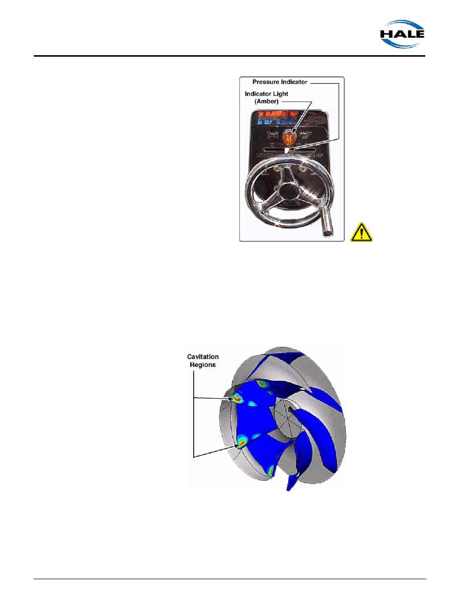
3.4
CAVITATION
(See Figure 3-5: “Sample,
Cavitation Regions.”)
Cavitation can occur while
pumping from draft, in relay, or
from a hydrant. The operator
must be aware of the warning
signs and immediately correct
the situation.
Cavitation can damage the
impeller and other sensitive
components, impair pump per-
formance, and reduce flow
capacity. The damage done
during any one period of cavi-
tation is not great, but the
effects are cumulative. Implosions occurring during cavitation break away
or erode tiny pieces of metal from the internal parts and the pump casing.
When enough metal has been chipped away, the impeller becomes unbal-
anced causing a strain and vibration on bearings, bushings and shafts.
Figure 3-4: TPM Relief
Valve Control
Figure 3-5: Sample, Cavitation Regions