Switching characteristics - serial audio ports, Cs8427 – Cirrus Logic CS8427 User Manual
Page 8
CS8427
8
DS477F5
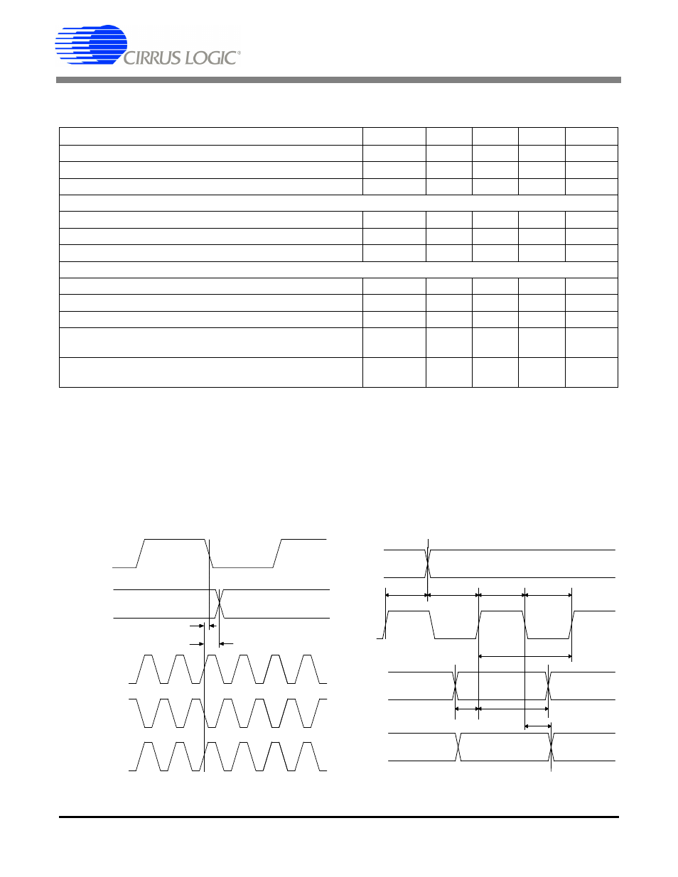
SWITCHING CHARACTERISTICS - SERIAL AUDIO PORTS
Inputs: Logic 0 = 0 V, Logic 1 = VL+; C
L
= 20 pF.
Notes: 8. The active edges of ISCLK and OSCLK are programmable.
9. When OSCLK, OLRCK, ISCLK, and ILRCK are derived from OMCK they are clocked from its rising
edge. When these signals are derived from RMCK, they are clocked from its falling edge.
10. The polarity of ILRCK and OLRCK is programmable.
11. No more than 128 SCLK per frame.
12. This delay is to prevent the previous I/OSCLK edge from being interpreted as the first one after I/OLRCK
has changed.
13. This setup time ensures that this I/OSCLK edge is interpreted as the first one after I/OLRCK has
changed.
Parameter
Symbol Min Typ
Max
Units
OSCLK Active Edge to SDOUT Output Valid
t
dpd
-
-
20
ns
SDIN Setup Time Before ISCLK Active Edge
t
ds
20
-
-
ns
SDIN Hold Time After ISCLK Active Edge
t
dh
20
-
-
ns
Master Mode
O/RMCK to I/OSCLK active edge delay
(Note 8, 9)
t
smd
0
-
10
ns
O/RMCK to I/OLRCK delay
t
lmd
0
-
10
ns
I/OSCLK and I/OLRCK Duty Cycle
-
50
-
%
Slave Mode
I/OSCLK Period
t
sckw
36
-
-
ns
I/OSCLK Input Low Width
t
sckl
14
-
-
ns
I/OSCLK Input High Width
t
sckh
14
-
-
ns
I/OSCLK Active Edge to I/OLRCK Edge
t
lrckd
20
-
-
ns
I/OLRCK Edge Setup Before I/OSCLK Active Edge
t
lrcks
20
-
-
ns
sckh
sckl
sckw
t
t
t
tdpd
SDOUT
(input)
(input)
SDIN
dh
t
ds
t
lrcks
t
lrckd
t
ISCLK
OSCLK
ILRCK
OLRCK
t sm d
t lmd
H a rdw a re M o de
S oftw are M o de
IS C L K
O S C L K
(ou tp ut)
ILR C K
O L R C K
(ou tp ut)
R M C K
(ou tp ut)
R M C K
(ou tp ut)
O M C K
(inp ut)
Figure 1. Audio Port Master Mode Timing
Figure 2. Audio Port Slave Mode and Data Input Timing