2 reserving the first 5 bytes in the e buffer, 3 serial copy management system (scms), 4 channel status data e buffer access – Cirrus Logic CS8427 User Manual
Page 53: Figure 28, Figure 29, Cs8427
CS8427
DS477F5
53
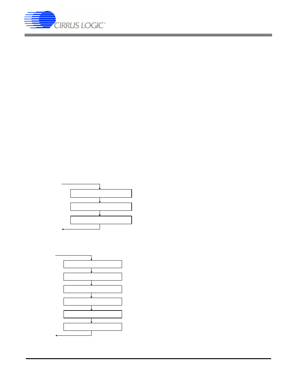
For writing, the sequence starts after a E to F trans-
fer, which is based on the output timebase. Since
a D to E transfer could occur at any time (this is
based on the input timebase), then it is important
to inhibit D to E transfers while writing to the E buff-
er until all writes are complete. Then wait until the
next E to F transfer occurs before enabling D to E
transfers. This ensures that the data written to the
E buffer actually gets transmitted and not overwrit-
ten by a D to E transfer.
If the channel status block to transmit indicates
PRO mode, then the CRCC byte is automatically
calculated by the CS8427, and does not have to be
written into the last byte of the block by the host mi-
crocontroller.
19.1.2 Reserving the first 5 bytes in the E
buffer
D to E buffer transfers periodically overwrite the
data stored in the E buffer. This can be a problem
for users who want to transmit certain channel sta-
tus settings which are different from the incoming
settings. In this case, the user would have to su-
perimpose his settings on the E buffer after every
D to E overwrite.
To avoid this problem, the CS8427 has the capa-
bility of reserving the first 5 bytes of the E buffer for
user writes only. When this capability is in use, in-
ternal D to E buffer transfers will NOT affect the
first 5 bytes of the E buffer. Therefore, the user can
set values in these first 5 E bytes once, and the set-
tings will persist until the next user change. This
mode is enabled by the Channel Status Data Buff-
er Control register.
19.1.3 Serial Copy Management System
(SCMS)
In software mode, the CS8427 allows read/modi-
fy/write access to all the channel status bits. For
consumer mode SCMS compliance, the host mi-
crocontroller needs to read and manipulate the
Category Code, Copy bit and L bit appropriately.
In hardware mode, the SCMS protocol can be fol-
lowed by either using the COPY and ORIG input
pins, or by using the C bit serial input pin. These
options are documented in the hardware mode
section of this data sheet.
19.1.4 Channel Status Data E Buffer
Access
The E buffer is organized as 24 x 16-bit words. For
each word the MS Byte is the A channel data, and
the LS Byte is the B channel data (see
There are two methods of accessing this memory,
known as one byte mode and two byte mode. The
desired mode is selected through a control register
bit.
One Byte Mode
In many applications, the channel status blocks for
the A and B channels will be identical. In this situ-
ation, if the user reads a byte from one of the chan-
nel's blocks, the corresponding byte for the other
channel will be the same. Similarly, if the user
wrote a byte to one channel's block, it would be
necessary to write the same byte to the other
block. One byte mode takes advantage of the often
identical nature of A and B channel status data.
Figure 28. Flowchart for Reading the E Buffer
D to E interrupt occurs
Optionally set D to E inhibit
Read E data
If set, clear D to E inhibit
Return
E to F interrupt occurs
Optionally set E to F inhibit
Clear D to E inhibit
If set, clear E to F inhibit
Return
Set D to E inhibit
Write E data
Wait for E to F transfer
Figure 29. Flowchart for Writing the E Buffer