Cs8427, 11 interrupt 2 mask (0ch), 13 receiver channel status (0fh) (read only) – Cirrus Logic CS8427 User Manual
Page 34
CS8427
34
DS477F5
11.11 Interrupt 2 Mask (0Ch)
The bits of this register serve as a mask for the Interrupt 2 register. If a mask bit is set to 1, the error is unmasked,
meaning that its occurrence will affect the INT pin and the status register. If a mask bit is set to 0, the error is masked,
meaning that its occurrence will not affect the INT pin or the status register. The bit positions align with the corre-
sponding bits in the Interrupt 2 register. This register defaults to 00h.
11.12 Interrupt 2 Mode MSB (0Dh) & Interrupt 2 Mode LSB (0Eh)
The two Interrupt Mode registers form a 2-bit code for each Interrupt Register 1 function. There are three ways to
set the INT pin active in accordance with the interrupt condition. In the Rising edge active mode, the INT pin be-
comes active on the arrival of the interrupt condition. In the Falling edge active mode, the INT pin becomes active
on the removal of the interrupt condition. In Level active mode, the INT interrupt pin becomes active during the in-
terrupt condition. Be aware that the active level (Active High or Low) only depends on the INT[1:0] bits. These reg-
isters default to 00.
00 - Rising edge active
01 - Falling edge active
10 - Level active
11 - Reserved
11.13 Receiver Channel Status (0Fh) (Read Only)
The bits in this register can be associated with either channel A or B of the received data. The desired channel is
selected with the CHS bit of the Channel Status Data Buffer Control Register.
AUX3:0 - Incoming auxiliary data field width, as indicated by the incoming channel status bits, decoded according
to IEC60958 and AES3.
0000 - Auxiliary data is not present
0001 - Auxiliary data is 1 bit long
0010 - Auxiliary data is 2 bits long
0011 - Auxiliary data is 3 bits long
0100 - Auxiliary data is 4 bits long
0101 - Auxiliary data is 5 bits long
0110 - Auxiliary data is 6 bits long
0111 - Auxiliary data is 7 bits long
1000 - Auxiliary data is 8 bits long
1001 - 1111 Reserved
PRO - Channel status block format indicator
0 - Received channel status block is in consumer format
1 - Received channel status block is in professional format
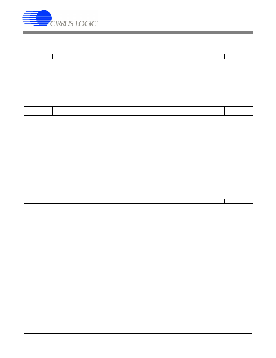
7
6
5
4
3
2
1
0
0
0
0
0
DETUM
EFTUM
QCHM
0
7
6
5
4
3
2
1
0
0
0
0
0
DETU1
EFTU1
QCH1
0
0
0
0
0
DETU0
EFTU0
QCH0
0
7
6
5
4
3
2
1
0
AUX3
AUX2
AUX1
AUX0
PRO
AUDIO
COPY
ORIG