Figure 10, Figure 9, Shows t – Cirrus Logic CS8427 User Manual
Page 21: Figure, T pll, Figure 12, Shows a standard aes3, Cs8427
CS8427
DS477F5
21
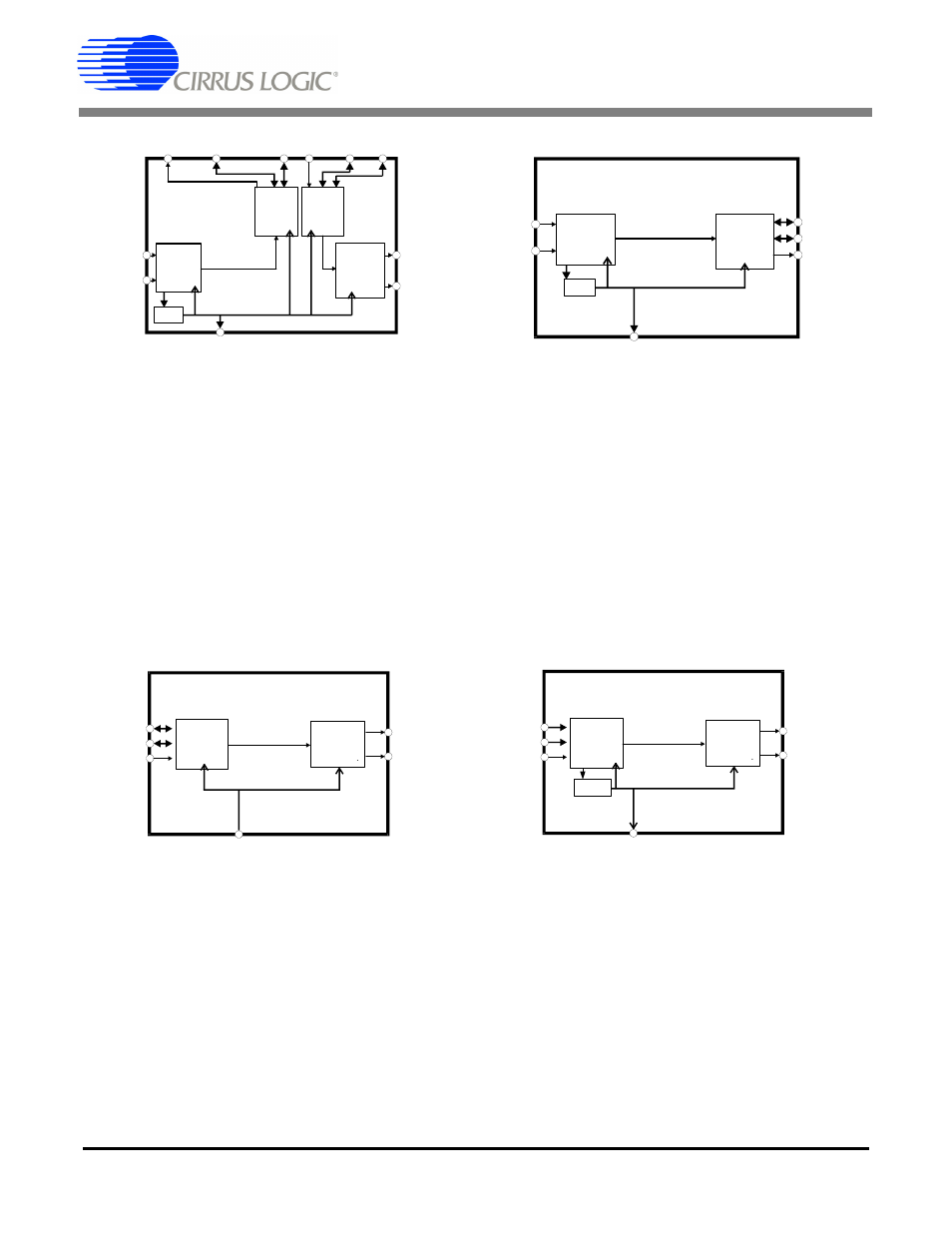
AES3
Encoder
& Driver
Serial
Audio
Output
OLRCK
OSCLK
SDOUT
TXP
TXN
PLL
RMCK
TXD1-0:
SPD1-0:
OUTC:
INC:
RXD1-0:
01
10
1
0
01
Clock Source Control Bits
Data Flow Control Bits
AES3
Rx &
Decode
RXP
RXN
Serial
Audio
Input
ILRCK
ISCLK
SDIN
Figure 9. AES3 Input to Serial Audio Output,
Serial Audio Input to AES3 Out
NOTE: Applications implementing both the Seri-
al Audio Output Port and the AES3 Transmitter
must operate at the same sample rate because
they are both controlled by the same clock
source.
OMCK
TXD1-0:
SPD1-0:
OUTC:
INC:
RXD1-0:
01
01
0
1
00
Clock Source Control Bits
Data Flow Control Bits
AES3
Rx &
Decode
I LRCK
I SCLK
SDIN
TXP
TXN
Serial
Audio
Input
Figure 11. Input Serial Port to AES3 Transmitter
without PLL
Serial
Audio
Output
OLRCK
OSCLK
SDOUT
PLL
RMCK
TXD1-0:
SPD1-0:
OUTC:
INC:
RXD1-0:
10
10
1
0
01
Clock Source Control Bits
Data Flow Control Bits
AES3
Rx &
Decode
RXP
RXN
TXOFF : 1
Figure 10. AES3 Input to Serial Audio Output Only
RMCK
TXD1-0:
SPD1-0:
OUTC:
INC:
RXD1-0:
01
01
1
0
00
Clock Source Control Bits
Data Flow Control Bits
AES3
Rx &
Decode
I LRCK
I SCLK
SDIN
TXP
TXN
Serial
Audio
Input
PLL
Figure 12. Input Serial Port to AES3 Transmitter
with PLL
NOTE: In this mode, ILRCK and ISCLK are
inputs only.