1 aes3 transmitter external components, 2 isolating transformer requirements, Appen – Cirrus Logic CS8427 User Manual
Page 50: For a, Appendix a, Appendix a: external, Cs8427
CS8427
50
DS477F5
18. APPENDIX A: EXTERNAL
AES3/SPDIF/IEC60958 TRANSMITTER
AND RECEIVER COMPONENTS
This section details the external components re-
quired to interface the AES3 transmitter and re-
ceiver to cables and fiber-optic components.
18.1 AES3 Transmitter External
Components
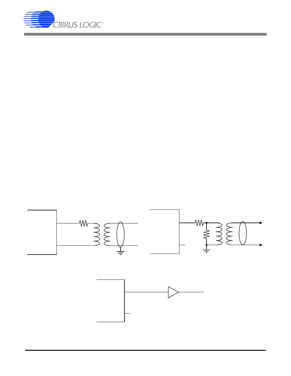
The output drivers on the CS8427 are designed to
drive both the professional and consumer interfac-
es. The AES3 specification for professional/broad-
cast use calls for a 110
Ω source impedance and a
balanced drive capability. Since the transmitter
output impedance is very low, a 110
Ω resistor
should be placed in series with one of the transmit
pins. The specifications call for a balanced output
drive of 2-7 V peak-to-peak into a 110
Ω load with
no cable attached. Using the circuit in
the output of the transformer is short-circuit pro-
tected, has the proper source impedance, and pro-
vides a 5 V peak-to-peak signal into a 110
Ω load.
Lastly, the two output pins should be attached to
an XLR connector with male pins and a female
shell, and with pin 1 of the connector grounded.
In the case of consumer use, the IEC60958 speci-
fications call for an unbalanced drive circuit with an
output impedance of 75
Ω and a output drive level
of 0.5 V peak-to-peak ±20% when measured
across a 75
Ω load using no cable. The circuit
shown in Figure 21 only uses the TXP pin and pro-
vides the proper output impedance and drive level
using standard 1% resistors. If VL+ is driven from
+3.3 V, use resistor values of 243
Ω and 107 Ω.
The connector for a consumer application would
be an RCA phono socket. This circuit is also short
circuit protected.
The TXP pin may be used to drive TTL or CMOS
gates as shown in Figure 22. This circuit may be
used for optical connectors for digital audio since
they usually have TTL or CMOS compatible inputs.
This circuit is also useful when driving multiple dig-
ital audio outputs since RS422 line drivers have
TTL compatible inputs.
18.2 Isolating Transformer Requirements
Please refer to the application note AN134: AES
and SPDIF Recommended Transformers for re-
sources on transformer selection.
110-(R
TXP
+R
TXN
)
TXP
TXN
XLR
1
CS8427
Figure 20. Professional Output Circuit
Figure 21. Consumer Output Circuit
374-R
TXP
90.9
Ω
TXP
TXN
RCA
Phono
CS8427
Figure 22. TTL/CMOS Output Circuit
TXP
TXN
TTL or
CMOS Gate
CS8427