Winland Electronics EA800-ip User Manual
Page 26
26
D-011-0152
Connecting Wired Sensors
6.
After connecting the wire ends to the terminal block, align the terminal block to the correct header pins, and
press it fully onto the header connector pins.
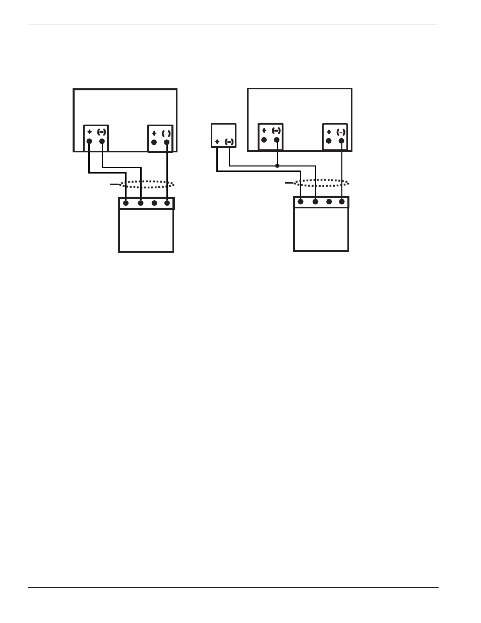
Figure 11 EA800 Console Wired HA-III+ Sensor Connections
J6
Input N
User
supplied
cable
HA-III+
Connector
P
o
w
er Input
GND
SINK
SOURCE
NC
NC
J5
Aux Power Out
EA800 Console
J6
Input N
User
supplied
cable
HA-III+
Connector
P
o
w
er Input
GND
SINK
SOURCE
NC
NC
J5
Aux Power Out
External
Power
Adapter
EA800 Console
Console-Powered
External Adapter-Powered
Note:
In this diagram, NC indicates “no connection.”