Winland Electronics EA800-ip User Manual
Page 12
12
D-011-0152
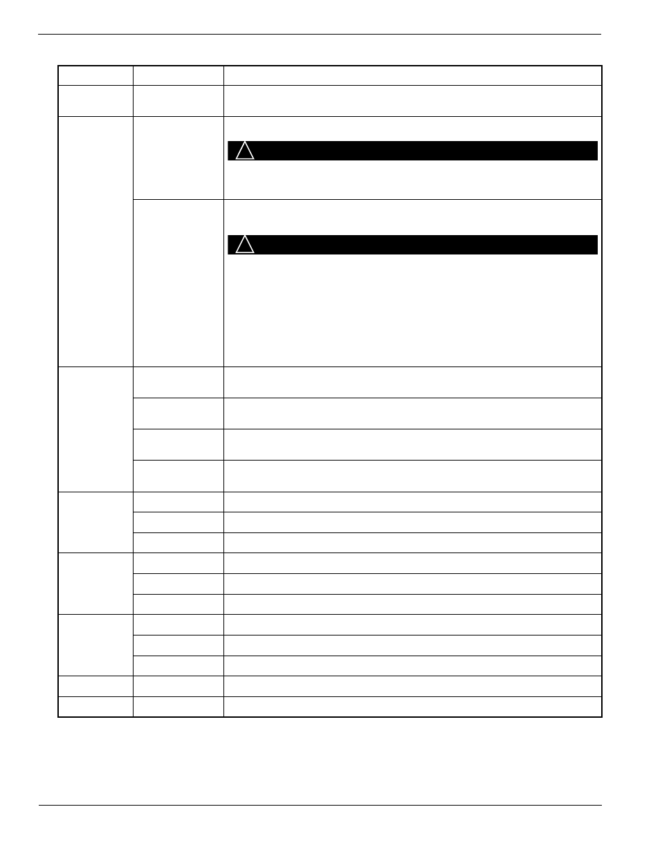
Console Connections
Table 3
EA800 Console Connector Functions
Connector
Designation
Function
J2
USB
USB Type A connection used to program firmware, export logs, and export
and import configuration files.
J5
Power In
11-26 VDC input power connection for EA800 console (from accessory power
supply or alarm panel).
CAUTION
!
CAUTION
Observe (+) and (-) polarity markings on circuit board. EA800 can be
damaged if power polarity is reversed.
Aux Power Out
11-26 VDC power out connection for EA800 accessories requiring power
(such as HA-III+ Humid Alert). This output voltage equals that of Power In and
is current-limited to a maximum of 500 mA.
CAUTION
!
CAUTION
Connect only accessories specified in this manual to the Aux Power Out
connection. Connection of unsuitable loads to this connection may
damage the power supply and EA800, or result in improper or unreliable
operation.
Note: Accuracy for the HA-III+ sensor is specified at 12VDC.
If Aux Power Out is used to power the HA-III+ and is above
12VDC, then the accuracy of the HA-III+ is compromised.
J6
INPUT 1
Wired input for Sensor 1 external temperature, water, 4-20mA, dry contact, or
humidity sensor.
INPUT 2
Wired input for Sensor 2 external temperature, water, 4-20mA, dry contact, or
humidity sensor.
INPUT 3
Wired input for Sensor 3 external temperature, water, 4-20mA, dry contact, or
humidity sensor.
INPUT 4
Wired input for Sensor 4 external temperature, water, 4-20mA, dry contact, or
humidity sensor.
J8
OUTPUT 1
Form C relay alarm output for Relay 1. Corresponds to wired input 1.
OUTPUT 2
Form C relay alarm output for Relay 2. Corresponds to wired input 2.
OUTPUT 3
Form C relay alarm output for Relay 3. Corresponds to wired input 3.
J9
OUTPUT 4
Form C relay alarm output for Relay 4. Corresponds to wired input 4.
OUTPUT 5
Form C relay alarm output for Relay 5. Corresponds to wireless input 5.
OUTPUT 6
Form C relay alarm output for Relay 6. Corresponds to wireless input 6.
J10
OUTPUT 7
Form C relay alarm output for Relay 7. Corresponds to wireless input 7.
OUTPUT 8
Form C relay alarm output for Relay 8. Corresponds to wireless input 8.
AUX OUT
Form C relay output that activates upon an alarm from any of the sensors.
J13
Antenna
RF receive and transmit
J14
Antenna
RF receive and transmit