Power supply / sensor voltage selection – Winland Electronics EA800-ip User Manual
Page 17
General Information
D-011-0152
17
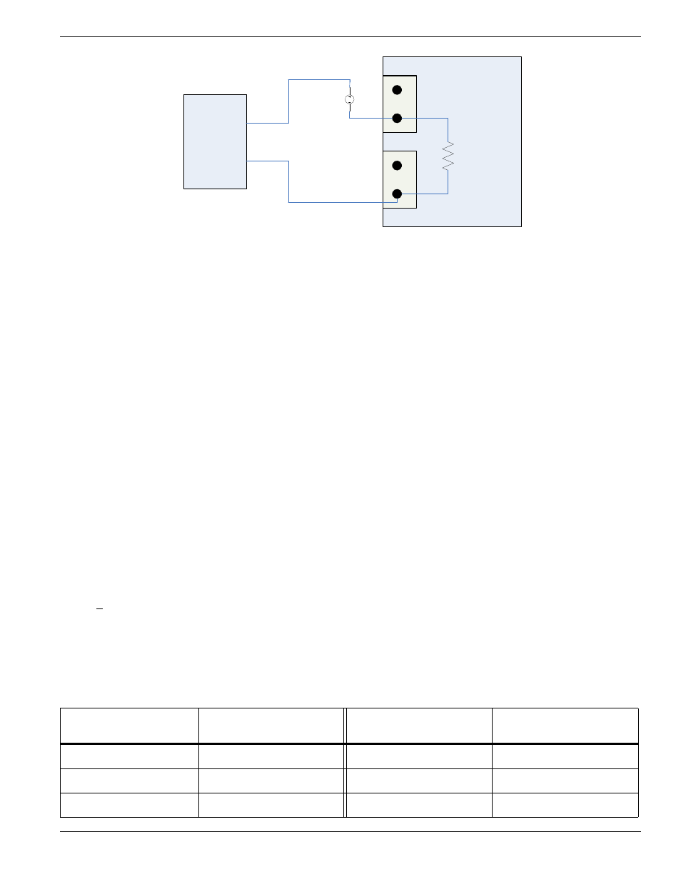
Figure 7 4-20mA Sensor Wiring Diagram - External Power Supply
Power Supply / Sensor Voltage Selection
In order to determine the power supply voltage necessary to ensure correct full-scale operation, it is necessary to
identify all voltage drops within the current loop.
Figures 6 and 7 show an EA800 drop of 4.0 VDC. This value accounts for the voltage drop generated by
connecting the 4-20mA sensor to the EA800 using 1000 feet of 22 AWG wire.
Now it is only necessary to identify the operating voltage range of the 4-20mA sensor, more importantly the
minimum operating voltage. Once identified, the minimum operating voltage of the sensor can be added to the
4.0V voltage drop of the EA800 (+ wire) to determine the power supply voltage necessary to ensure correct
full-scale operation.
Example:
■
Assume that a 4-20mA sensor whose operating input voltage range is 10 – 30V has been selected for use.
Therefore the minimum operating voltage of the sensor is 10V (V
sensor
). When the 4.0V drop of the EA800
(and wire) is added, it can be determined that at least 14VDC is needed to power the loop.
■
If the EA800 is connected to a 12VDC power supply, use of the sensor in this example requires an external
power supply of at least 14V as shown in Figure 7.
It is important to not exceed the maximum operating voltage of the 4-20mA sensor, as specified within the sensor’s
product specification.
The following formula provides the basis for the selection matrix shown in Table 7. Please use Table 7 to select
either the proper sensor rating to be used with a known power supply, or select a power supply for a known sensor
rating.
R
L
< (V
cc
– x) .023
where:
■
R
L
= Loop resistance of 200
Ω
■
V
cc
= Power supplied to EA800 or Aux Power Out
■
X = Sensor voltage (max)
Table 7
4-20mA Voltage Select Matrix
Power Supplied to EA800
or AUX. Power Out
V
sensor
(max.) [Maximum
sensor voltage rating]
Power Supplied to EA800 or
AUX. Power Out
V
sensor
(max.) [Maximum
sensor voltage rating]
11 VDC
7 VDC
19 VDC
15 VDC
12 VDC
8 VDC
20 VDC
16 VDC
13 VDC
9 VDC
21 VDC
17 VDC
+
DC
External
Supply
+
-
4.0V
200
ohms
Aux Power
J5
+
(-)
+
(-)
Input N
J6
+
-
Vsensor
4-20 mA
Transmitter
EA800
If Vsensor > 8 V and Aux Power
= 12V
Max load of 200
ohms includes
1000 ft. (304.5
m) of 22 AWG
(2-conductor)
wire connecting
the EA800 to the
4-20mA sensor
Note: Wiring shown inside this box
is internal to EA800.
No additional wiring is required.